Thoughts & musings from a product developer and manager
Adding a DIY PID to the Gaggia Classic Pro
Reads:185,252
The Gaggia Classic is a very capable espresso machine that gets even better with a couple of improvements. Once the machine has been set to 9 bars of pressure (see bottom of article), the next big improvement is the addition of a PID. This gives the machine a whole new level of consistency, and gives you fine control over brew temperature. Here’s how to install a PID on the Gaggia Classic Pro.
There are several PID kits that are available for the Gaggia, the most popular ones are by Mr. Shades and Auber Instruments.
However, at the cost of convenience, these kits can be relatively expensive. On top of the original price tag, international shipping, taxes, duties and currency exchanges can make obtaining these kits time consuming and even more expensive.
I decided to go the do-it-yourself route, ordering the parts separately, at a fraction of the cost of the kits. I installed the PID so that there are no permanent modifications to the machine, and the Gaggia can be returned to factory condition at any time. Because there is very little information on how to install a PID on the latest generation of the New Classic (2018 and newer, also called the Gaggia Classic Pro in North America), here are instructions on to do this.
In a nutshell, the Gaggia Classic thermostat is replaced by the combination of the the thermocouple, the PID, and the solid state relay.
Before and after installation of the PID, simplified
The required parts are a PID controller, a solid state relay (SSR) preferably rated for 40 amps, a K-type thermocouple, a thermocouple adapter to connect the thermocouple to the Gaggia boiler, wire rated for mains voltages as well as some smaller gauge 12 volt wire, male and female quick disconnect connectors, spade connectors, and two piggyback spade connectors. Because the PID runs on mains voltages, an enclosure is required. Zip ties, heat shrink tubing, thermal paste, double sided tape, and a bolt and nut to attach the SSR are also required.
PID: I chose the REX-C100, which I ordered as an inexpensive kit with a thermocouple and a solid state relay [link updated 7/23/2025, original listing link is broken]. The REX-C100 PID is frequently used in espresso machines. It’s inexpensive and works well for this purpose. The kit ended up being cheaper to order than sourcing the parts separately. The 40 amp SSR that comes with the kit works well too. The problem with the kit that I ordered (and the problem with any PID kit, as far as I can tell) is that the included thermocouple is permanently attached to a threaded adapter that will not fit into the Gaggia’s threaded thermostat connector. To get around this, I had to order a separate thermocouple and adapter (see below).
K-type thermocouple: I ordered a separate K-type thermocouple, without an adapter. These are fairly inexpensive due to the demand from the 3D printing community. This one from Banggood fits into threaded adapters (see below), and is inexpensive.
Thermocouple adapter: the Gaggia boiler thermostats have M4 threads, so you need an adapter to connect the thermocouple to the boiler. Thankfully the 3D printing community uses all kinds of thermocouples and adapters, so these adapters can be relatively easily found. This thermocouple adapter works well.
To avoid having to make any permanent modifications to the Gaggia, a couple of piggyback spade connectors will let you tap into the power cables without having to cut any wires.
There are very few enclosures that offer a perfect fit. A 1/16 extruded aluminium case offers the best fit and finish, but they are very hard to find. If you have access to a 3D printer, a case can be printed. Here are the STL files I adapted: enclosure, and lid.
Warning! This process involves working with potentially lethal mains-level voltages. Always work with the Classic unplugged. Do not undertake this procedure if you are not comfortable or uncertain.
Note: I fully tested the PID, SSR and thermocouple on the workbench before final installation. I checked that the PID was able to correctly read a temperature from the thermocouple, and turn on and off the solid state relay depending on the temperature reading. Because the wiring connections can vary between manufacturers, you should bench-test your setup before final assembly.
Here are the installation steps:
Unplug the Gaggia Classic. This is VERY important! You will be working with potentially lethal mains voltages. Do not work with the Classic plugged in.
Remove the portafilter and water tank.
Remove the cover assembly and filler funnel by unscrewing the two small screws at the rear of the top. Pull the cover assembly off by pulling upwards, and disconnect the ground cables. Set the cover and screws aside.
Pull off the steam knob and disconnect the steam wand. Although this is optional, it is difficult to access the power switch to tap power for the PID, and it is almost impossible to reach the thermostat without moving the boiler, and the boiler can’t be moved unless the steam wand is removed. To do this, loosen the nut connecting the steam wand to the steam control assembly. Pull the steam wand up and out of the Classic, and set it aside.
Loosen the four bolts that hold down the boiler assembly. These are located around the shower screen. Once these bolts are removed, the boiler can be moved around without having to disconnect any hoses or wires.
Tap the switched hot/load mains power: disconnect the lower left-hand (if facing the front of the machine) wire from the power switch. Plug in a mains-rated cable connected to a piggyback spade connector, and then plug the original switched mains cable into the piggyback. I hesitate to identify wires by their color, as the wire colors in the Gaggia seem to vary from year to year and from region to region. I strongly suggest checking which switch terminal switches the mains. Run this wire along the rest of the existing cables and out the back of the Classic, through one of the vent slots. Leave this cable longer than needed for now, it will be trimmed and terminated later.
Tap the neutral mains: disconnect the lower wire from the mains connector at the back of the Classic. Double check that this is the neutral! Plug in a mains-rated wire connected to a piggyback spade connector, and then plug the original neutral cable into the piggyback. Again, as above, run this cable out the back, and leave it unterminated and longer than needed.
Disconnect the two connectors from the brew thermostat, which is located on the bottom left-hand side of the boiler as you face the machine. This is probably the most difficult part of the installation. These connectors are hard to reach, and are on very tight. Using pliers to pull the connectors can pinch them on even more tightly, making them extremely difficult to remove. I found that carefully pushing the boiler up gives better access to the thermostat, either from above, or by reaching up from below. Be careful, the edges of the hole in the chassis are very sharp. Wear a glove when reaching in from below, otherwise bloodletting is likely.
Pull the two wires that you removed from the thermostat up to the top of the machine, near the rest of the wires that run from the front to the back of the machine. These wires will be connected to the solid state relay later on, so they no longer need to be in the bottom of the machine.
Remove the thermostat. It’s threaded on, and should not be very tight. Leave as much of the thermal grease in place as possible. Keep the thermostat, in case you want to return the Classic back to factory condition.
Thread in the M4 thermocouple adapter in the place of the thermostat. Do not over-tighten the adapter, it only needs to be finger-tight.
Slip some heat shrink tubing over the thermocouple, and ideally dip the thermocouple tip in some thermal grease, then insert the thermocouple into the adapter. Heat the shrink tubing.
Thread the thermocouple wire through to the back of the machine, and out the same slot as was used for the other wires. If the thermocouple wire is too long, coil it up inside the machine, well away from the boiler or any uninsulated connections, using zip ties to hold the coil in place.
Using two 5-8 cm pieces of properly-rated wire (15 amps for North America), make two connectors to connect the thermostat wires to the AC terminals of the solid state relay. One end of the wire should be a male disconnect connector, and the other end should be a spade connector. Tighten one end of your connector down to one of the solid state relay’s AC (~) terminals and plug the other end into one of the disconnected thermostat wires. Do the same with the other connector wire. It doesn’t matter which thermostat wire is connected to which of the AC terminals on the solid state relay.
Run two 12 volt wires from the + and – terminals of the solid state relay and out the back of the Classic, again using the same slot.
Attach the solid state relay to the inside back wall of the Classic, using a small bolt and nut. It should be placed as close to the left-hand side of the Classic as possible. Most assembly guides recommend using some thermal paste between the SSR and the Classic to ensure that any heat from the SSR is dumped to the chassis.
Make sure that all the new and repositioned wires are cleanly routed away from the boiler and pump and any uninsulated connectors. A couple of zip ties come in handy here. You should now have two mains wires, two 12 volt wires, and the shielded thermocouple wire running out of the back of the Classic.
Re-attach the boiler with the four bolts, re-attach the steam wand, push on the steam knob, and put the lid assembly back on, without forgetting to re-connect the two ground wires.
Trim, terminate and connect the wires you routed out the back of the Classic to the PID. Depending on the enclosure, you may need to insert the PID into the housing first. The two mains wires connect to terminals 1 and 2 (starting counter-clockwise from top-left). It doesn’t matter which mains terminal is connected to hot and which one is connected to neutral. The 12 volt wires from the SSR connect to terminals 4 and 5. The thermocouple connects to terminals 6 and 7. Make sure the polarity for the SSR and thermocouple wires is correct, this is important.
Close the PID enclosure, and attach it to the side of the Classic. Double sided tape will work.
You should be done! If the wiring was done correctly, the PID should power up when the Classic is turned on.
The REX-C100 should work out of the box, set for heating mode, with alarms disabled, and units set to Celsius. However, depending on the seller, some settings may need to be changed. Consult the instructions that came with your PID to make sure.
The default target temperature on the PID will almost certainly not be correct. For the Gaggia Classic, taking into account the temperature drop between the boiler and the group head (5-8 degrees C), the PID target temperature should be set to about 103 degrees C or 220 degrees F at sea level.
To set the target temperature, press the ‘Set’ button on the front of the panel. Then use the cursor keys to select the digits to increase and decrease.
Leave the Classic powered on for at least 15 minutes. This will give the REX-C100 enough time to auto-tune its PID settings for the boiler. When the temperature stabilizes to within 1 degree of the target temperature, the auto-tuning is complete.
Brew away!
Final note: before going down the PID route, the easiest modification to make, and the best starting point for Gaggia Classic modifications, is lowering the brew pressure. The Classic’s over-pressure valve (OPV) is set to 14 bars, which is a pressure better suited to the use of pressurized portafilters. For espresso, 9 bars is the generally preferred pressure. For the Classic Pro, this requires either shortening the spring in the OPV valve through trial and error, or ordering a spring kit from Mr. Shades.
168 thoughts on “Adding a DIY PID to the Gaggia Classic Pro”
Hey Chris,
Thanks heaps for the detailed instructions. I plan to do this shortly for my old gaggia classic. Would you be able to post starting values for the PID kit please?
I’ve been reading up many different values for the P, I and D, and i’m not sure where to start.
Cheers.
Hi Nish. I have not changed any of the P, I or D settings on my controller. The factory settings have been working well for me, aside from a ~5 degree C overshoot when it first reaches the target temperature. Once warmed up, the recovery time is quick and the swing is fairly minimal. Maybe I’m missing something?
Nevertheless, I will take a look and see what values my controller is set to.
Hi Chris, I’ve followed these instructions exactly (thank you for your thoroughness) except for how the mains were tapped: I moved the two wires terminating on the bottom of the power switch to the top, and tapped them (as per another guide…)
I’m running into problems and I don’t know if my REX-C100’s starting values are the problem or if its my deviation with the wiring: Regardless of the temperature that i set on my PID, toggling the Gaggia ‘on’ causes it to climb to 150-160C and then slowly decline to 118-125C, at which time it will heat up again. I’ve noticed that the PID’s ‘output1’ LED isn’t illuminated after it climbs above my set temperature (103) but the boiler is getting heated up regardless. Any ideas? I had to manually enable autotuning on my REX-C100 and i don’t know if other values are screwed up or if its something else, since it really does seem like the boiler is getting power in bypass of whatever the PID is doing.
It looks like your GC is in steam mode. What you describe looks very much like the steam thermostat cycle. Did you reverse any wires to the steam switch? I am not sure exactly what you did when you moved the wires terminating on the bottom of the power switch. Fortunately, no damage done, and you can easily revert your changes.
Thanks for your reply: I think you are correct about the Gc being stuck in steam mode, but I never touched the steam switch’s wires and reverting the top/bottom swap on the power switch didn’t solve the issue. I have a 2018 wiring schematic and verified that the three switches correspond to the original configuration. I’m tempted to return the GC because I never used it prior to the mod and it may have been a pre-existing issue….
There is definitely something weird going on. It would be great to see how the machine is behaving without the PID, to get a baseline.
I’m wondering if this could somehow be the outcome of a bad SSR: I’m not seeing current flow between the two AC terminals of the SSR when the PID is attempting to heat the boiler to the Set Temp. The LED on the SSR is functioning but no current can be seen. Even if that is the case, i don’t have a clue as to why i would be in steam mode, since i didn’t touch the steam mode button or its wires, i have already reverted my swap of the power switches wires (just from up to down on the same switch so that shouldnt have impacted anything) and i’ve validated that the rollback was correct with a multimeter. I also checked to ensure that the physical steam switch is functioning correctly and the circuit is broken when it is off.
I’ve attached an album with my wiring below; I’ve literally had an engineer look at it and The Gaggia is 100% at its original state except for the power taps on the neutral at the plug, the live on the brew switch, and the thermocouple to SSR wiring: https://imgur.com/a/rc4xtfz
Your wiring looks right. I am going into speculation mode here… I wonder if your Gaggia came with the steam and brew thermostat positions reversed? That would be easy enough to verify with a multimeter, to see which thermostat is active in steam mode and which one is active in brew mode.
The SSR is just a fancy switch and it should only be turning on and off, so depending on how you measure you may not see current. You can verify the SSR by disconnecting its AC terminals and checking that it is indeed turning on and off.
CONCLUSION! The boiler had been installed in such a way that it had pinched/nearly severed the upstream wire on the brew light. It was impossible to see without getting down into the wire harness. Replacing that wire= everything works perfectly now!
Awesome! Glad things worked out.
Hi Peter. The C100 is probably made by dozens of different manufacturers. Always double-check your specific model’s wiring terminal layout and numbering scheme. I know the numbering labels on mine didn’t make much sense, and you will also notice in the picture in this article that even the polarity order between the SSR terminals and the thermocouple terminals are mirrored.
As for your PID always remaining on, it looks like you wired it to the unswitched mains, instead of the switched power. You should be able to find the switched mains with the help of a multimeter. You want to connect the PID’s mains power terminal to the side of the Gaggia power switch that cuts out power when the machine is off. If you used piggyback connectors, it should be a quick job to move the right one over to the correct switch terminal.
Hi Andrue. You are right, it’s an M4 thread, not M3. The listing shows both M3 and M4 options, and I typed the first one when I wrote the article. Thanks for the catch, I will correct the article.
Hi Ray. Unfortunately, no, you can’t use the factory sensor. The GC comes from the factory with a simple thermostat that turns on at a certain pre-set temperature, and turns off at another pre-set temperature. It’s not a sensor, it doesn’t send any information, it just switches on an off, at setpoints that you can’t adjust. If you go for a PID, you need to use a thermocouple.
Well I ordered the wrong thread. In the text it says M4, but on the picture, it highlights to use the M3…
I’m sorry about that, Eric. The image I used is wrong and confusing, and I have now updated it. Somebody else (Andrue) had also pointed this error out.
Hi Justin. I am flattered, but will have to pass. This is really a DIY project. It will void your warranty, the possibility for making errors or breaking things during installation is too high, and the amount of time it takes would make it cost prohibitive.
If you’re not comfortable installing this yourself, and taking on any followup maintenance, I think you would be much better off purchasing a machine that comes with a PID from the factory.
Hey Chris, I’m wanting to put the pid into an extended 3d printed driptray. If you had to recommend a single display PID, which one would you steer me to? Thanks in advance, this was a huge help!
Hi Miguel. The C-100 can accommodate only one sensor/SSR, so you would only set it for brew temperature. You can use the sensor reading on the PID display to know when to start steaming. The PID will be more or less bypassed when the steam switch is on, it will just stop trying to heat because the boiler will be over the PID’s target temperature.
Otherwise, as I said in instructions above, to set the brew temperature, press the ‘Set’ button on the front of the panel. Then use the left/right buttons to select the digits to increase and decrease, and the up/down buttons to change the digits. It’s pretty straightforward.
Brilliant article.
Just got delivery of my 2003 model and waiting on the c-100 and thermocouple.
Does the wiring you’ve supplied automatically shut the PID unit off when you engage the steam switch?
Hi Paul. The way I wired the PID leaves it powered on as long as the main power switch is on. When the steam switch is on, the PID stays on but because the boiler temperature in steam mode is much higher than the brew temperature of the PID, the PID provides no power to the SSR and heating element.
While the steam switch is engaged, the PID serves to provide a temperature reading of the boiler, which is great, because you can use that temperature reading to time when to start steaming for maximum steam performance.
Hi , I followed the instructions but the PID starts up with some number and it doesn’t look normal , LCD just keep blinking some numbers the goes of for a few seconds the I get some numbers for half a second, it’so quick I can’t tell what is displaying, could I have got the power wiring wrong or if the cable are higher AWG would it causes issue?
Hi Kez. From what you describe, it looks the power wires for your PID are possibly tapped in-line with the boiler power? This would explain the constant switching on and off. Try powering the PID directly from mains power, with just the thermocouple connected (disconnect the SSR). You should see a strange number when the PID first powers on, then after about 3-5 seconds it should switch to the temperature reading from the thermocouple. If the PID stays on when wired directly to mains power, you will need to figure out which power wire to tap into. It should be the power/mains line that comes out of the main power switch, but before the boiler.
So the above instructions might not apply to the UK, I have the GC2019 but the live connection was the top right on the power switch when switched on, bottom left caused the PID to flicker and not work as expected, I fixed my issue but now the PID readout is 103 Dec but the water is 80 degrees, didn’t think it would be off by this much. Is there a way to calibrate the read out close to the water out temperature
Feedback is that there are almost no two GCs with identical wiring, even units destined for the same power rating. Wire colors and positions seem to vary. Glad you got that sorted out.
I would be surprised if your water is 80 degrees coming out of the boiler with the PID set to 103, but it’s possible, depending on the thermocouple you’re using. This video clearly shows how to program in an offset on the Rex C-100: https://youtu.be/9aW8MfiKIPg?t=291.
I bought the same parts as you have reccomended in the article but have run into the issue that the thermocouple is too large to fit into the adapter (they’re approx the same OD). Did you have to alter your thermocouple at all to get it to fit into the adapter, like removing the cap on the end or something?
Hi Evan. The PID I ordered came as a package with a solid state relay and a thermocouple, but that thermocouple had too big a diameter to with the Gaggia. The thermocouple that I ordered fit into the threaded adapter without any modifications. You could definitely drill out the adapter a bit to get the thermocouple to fit. Brass is soft and easy to drill, and all the adapter needs to do is provide a connection between the thermocouple and the boiler, so there would be no hard in doing this.
Hi Eddie. That controller is an interesting find. You’re giving up one of the two temperature readouts, so you’ll probably only see the actual temperature, as opposed to the target temperature, and I guess you can switch between the two with a button press.
It should work as a replacement for the C-100 and SSR, but because the SSR is built into the PID, so your wiring will be a bit different. This PID-SSR combination does away with the 12v connection, and uses three wires for the mains power and SSR, with one wire shared between mains and the SSR output. You would need to put the boiler heater element between the controller terminals 2 and 3. But I would definitely read the instructions that come with whatever you receive!
Hi Eddie. I have re-read the specifications for this controller. The SSR is only rated for 5 amps. This won’t be enough for the boiler heating element. You need at least 20 amps. You would probably blow the fuse in this controller/SSR within seconds.
I think this is why using a separate SSR and controller is the only way to go. At the amperages required to control the boiler heating element, you need an SSR that has enough mass and exposed metal to be able to attach it to a heat sink.
Hello, there is another model without SSR built in with name 7100 instead of 7200. I think one of either is the one which Shades of Coffee is using.
By the way there are three options as 12V, 24V and 85-250V DC. Which one shall we buy? Thanks
Hello, thanks for the nice and valuable text. Mr Shades is selling many small items (piggyback, spade, thermal paste, power cable, rubber grommet etc.) under the name “replacement PID kit parts” with very low prices. I will purchase the PID kit with thermocouple and SSR from aliexpress and buy these rest small items from Mr. Shades. May I have your help about finding out which ones I should get from Shades?
Hi Murat. It would be almost impossible for me to give you a complete list of the parts from Mr Shades that you will need, as it will depend on the PID and SSR models you order. Most likely they will have the same connector types as the REX-C100, but it’s always possible that you will need different connectors depending on what you end up ordering.
At a minimum, I think you would need the following:
Rubber grommet
Thermal paste
Set of wires – brew kit
Red power cable (unfused or fused)
Thick red SSR output cables
Blue SSR input cables
SSR Mounting nut/washer/bolt set
I don’t see piggyback connectors on Mr Shades’ list, maybe those are part of the set of wires, but it’s not clear.
Thanks a lot for the answer.
I have found the exact PID unit which Mr Shades is using and purchased it beside the Rex C100 kit you mentioned above:
QB-T7100 48*24mm Programmable Digital PID Temperature Controller AC/DC 85-250V
Unlike the 7200 model, this one does not have SSR inside. My plan is to install the Rex C100 first using your instructions. Maybe then try QB-T7100 afterwards and if it works I will buy the external case which is sold seperately (QB looks nicer with small size and external case). My only concern is that Mr Shades has two types of SSR units 40AA and 40DA. Do you think this makes difference? Or do you think the same set will work with QB-T7100?
I plan on doing the same thing as you did, bought both PID simply because the QB-T7100 is slimmer the case is readily accessible from mr. shades, compared to the higher cost of 3d printing a case for the REX.
I wondered if you ended up testing both in the end. Did you have any problems or stumbled upon anything unexpected? Did you try with the SSR unit 40 DA or 40AA?
Thank you very much if you find the time to answer me 🙂
Shades uses an XMT7100 modified to run two SSR’s: a DA for the brew temp and an AA for the steam temp. You can mod the XMT7100 yourself but it requires soldering on the PCB, basically removing the onboard relay and then jumpering the empty terminals. It’s not hard if you know what you are doing and there is at least one youtube vid showing how it’s done.
The same can be done with the REX C100 but you need one with all 8 screw terminals (the second SSR for steam uses the alarm function which needs terminals #6 and #7) and these two are missing on some REX’s.
Perhaps you are refering to the video by Damian Witonski. that will make it where only one SSR is needed. different wiring though. however the one SSR is nice and the modification gives upgraded steam with the solder mod.
On thing I realised is that Mr Shades does not allow purchasing the parts seperately unless you already purchased the kit as a whole. You can only buy them as spare parts.
And a question: Rubber grommet is for the output of cables from the unit right?
Thanks
I am not surprised, Mr Shades runs an honest business, and those parts are being offered at low prices. I deliberately avoided looking at the Mr Shades kits and instructions when I wrote this article, I don’t want to steer people away from them. Their kit is convenient, and is the way to go if someone doesn’t feel ready to take on a 100% DIY project. The grommet is used where the wires go through the chassis. I did not use a grommet.
Hello, I acquired and prepared all cables and SSR unit thanks to your well prepared title above. I am now waiting for my PID unit and thermocouple with M4 head to arrive this week. I have installed the supply cable for PID unit using piggyback spade connectors. I tested the current with multimeter and it is showing DC 100V when I turn on the on-off switch. When I turn off, it goes back to zero. Does this mean that I have made the connection properly? One end is connected to the mains connector at the back (where it is showing N sign), the other end is connected to the back of the on off switch (as you showed on the picture above).
My only concern is the diagramm I downloaded from whole latte love shows different connections then what I have seen in my unit https://wiki.wholelattelove.com/File:GAGGIA_CLASSIC_2019_Wiring_Schematic.pdf
It shows that neutral cables coming from thermostats are connecting each other under the steam switch but mine are connected under the main switch. Do you think this makes a difference? Shall I connect it to terminal 5 or 2 of the on-off switch? (I believe it is currently on 5) Or shall I just keep it as it is, showing DC 100V when I turn the switch on?
One last question: Auber and Mr Shades are calling their sensors PT100 while mine is K type thermocouple. Do you think this makes difference? Thank you.
Hello again, I found out that connection I made was wrong. The PID unit did not turn on using the same terminal of your machine. In mine, correct terminal was crosswise of yours. The best way to find is: 1-Connect one cable to the mains connector at the back where it is showing N sign – meaning Neutral. (Markings can be found on front side of the plug) 2-Check the color of the cable which shows L sign on the plug- meaning Live. 3-Connect the other cable to the terminal on the on off switch, which is on top of or below the Live cable. This is because the switch is connecting the terminals vertically when it is turned on.
I am glad you solved the problem, Murat. I am beginning to suspect that Gaggia created as many combinations of wiring configurations and colors as they made machines. It’s crazy. I’m all for freedom of expression and creativity, but not when it might electrocute someone.
Hello Chry,
Thanks for sharing this awesome guide.
One question, Ever thought about adding a pre infusion feature? If so, any idea how it can be achieved? Pressure control could be super nice to have.
Hi Nitzan. I have briefly thought about pre-infusion but the REX C-100 is not capable of this. Adding pre-infusion would require either a different and significantly more sophisticated PID, or integration with something like a microcontroller. Either way, you are looking at a lot more complexity and cost. You could simulate pre infusion by briefly running the pump.
The same complexity applies to pressure control. If you really want these features, it’s probably time to think about upgrading your machine.
Whole Latte Love has a new video about preinfusion on the classic. Basically, instead of running the pump for a few seconds and then shutting it off (which dumps your pressure courtesy of the solenoid valve) you open the steam valve about 1/4 to half way, hit the brew switch and then slowly close the steam valve (about 5 seconds or so). This way you are not losing any pressure via the solenoid valve, you are just reducing the initial pressure to the puck by venting some of it through the steam wand.
Hi,
The Rex c-100 reads in Celsius only, would I be able to substitute this kit with:
(PID Temperature Controller Meter Indicator, Jaybva Digital Universal Thermostat C and Fahrenhe F Display SSR and Alarm Output 40A Solid State Relay and Thermocouple Probe Heat Sink Included)? This is sold on amazon
Specifications :
Power supply : 90-265V AC/DC
40A SSR Solid state relay included
Mounting Dimension: DIN: 1/16 (48mmX48mmX80mm)
Thermocouple included: M6*1 thread , K type , 2m cable
Display: Dual display for Fahrenheit(F) and Celsius(C)
Range: -1999 to 9999 (depends on the input signal)
Main Output: SSR: Open circuit: 4V, Closed Circuit: 24V40mA DC
Auto-tuning PID cooling/heating control
1 RELAY alarm: Normal open, capacity 250V/3A AC or 30V/3A DC
Accuracy: 0.2%
Universal Input: Thermo Resistor: PT100, Cu50 . Thermocouple: J,S,K,E,Wre3 ~ Wre25
Net Weight: about 150g
Individually PID control parameters
P, I, d, controlling period, digital filter coefficient, and more… (for control theory experts only)
SSR control ready to connect external Solid State Relay to handle High current. Applications
K type thermocouple, 0-500℃, 2m cable (6 feet).
Thanks for your time
Hi Brian. The PID kit you described should work, but like the C-100 kit the I used, the included thermocouple won’t fit in the Gaggia Classic. Note that according to this video: https://www.youtube.com/watch?v=UETVv0qgz-w, you can switch the C-100 between Celsius and Fahrenheit.
Hi Brian. Most guides recommend connecting the SSR to the Gaggia’s (metal) body with some thermal paste, and this mount then serves as a heat sink. So I would say yes, you should use a heat sink, but the Gaggia body conveniently provides you with that function.
Hello Chris,
I managed the brew side PID and digging in for the steaming side, using PID alarm function of my XMT 7100 unit. I purchased an AC to AC SSR (SSR 40AA) which will stabilise steaming temperatures in much smaller margins than the original steam thermostat. However I now need to connect steaming and brewing circuits in parallel rather than serial because steaming circuit will not be closed unless I turn on steaming switch and supply power to steaming SSR. Thus brewing circuit needs to be connected directly to the heating element, not over steaming circuit.
My problem is, unlike Rancilio Sylvia, heating element of Gaggia Classic Pro seems impossible to connect without cutting cables. I don’t want to void my warranty. Do you know how to do this? I think Mr Shades has managed to do this using only cables because I don’t think he instructs anything to void the warranty. Do you have any idea how to do? Thanks.
Hello Chris,
Awesome guide! Thanks for putting it together, this has helped me a lot in figuring out most of my doubts with a PID project for a Gaggia. I still have one question you may be able to answer.
My Gaggia Classic uses 18 awg wire for every connection inside. I’m assuming it should be fine as well to use 18 awg wire to wire the mains connections to the PID, and between the heating element and the SSR?
Between SSR and PID I was planning on using 22 awg wire given its a lower power requirement.
Thanks in advance!
Hi Jun, glad you found this helpful. You can use the same 18 gauge wire between the heating element and the SSR. You can get away with lighter gauge wire for the mains connection to the PID, as the PID draws very little current. I used lamp cord for this. The PID is really converting the mains voltage to 12VDC both for its internal operation and to drive the SSR, so the PID’s draw is quite small. Likewise, you can use 22 awg for the connection between the PID and the SSR.
Hi Chris, I appreciate your tutorials on the PID install. My question is where did you place the SSR, is it near the water spout, right side or in the back if you are facing the front of the machine? Thanks!
Hi Chris,
I just installed the pid on my Gaggia classic Pro following your instruction guide. I have a question on the pid, it is normal for the brew light to blink (off and) while it stabilizes to the target temperature. Thanks, David
Yes it is normal for the brew light to blink like this after you install a PID. The PID switches the power to the boiler heating element on and off a lot more frequently than the original mechanical thermostat.
Perfect, came back here to ask this question! My install went as smooth as I hoped… all my wire colours and locations were identical to yours (Phewf). I found that moving the boiler up and to the side allowed me to get to the thermostat from the bottom really easily vs. the top. Thanks again for the write up, I’ll be playing around with temperature for the next week!
Hi David. I started with 103, and bumped it up to 105. It will depend on the beans you use, and your palate. My experience, and that of others including a commenter on this article, is that I would not want to go lower than 103 on the Gaggia Classic. The 103 is not a true 103, that is what is getting measured in the boiler wall, and there is also a temperature drop off between the boiler and the portafilter, so your final espresso temperature will be lower.
The fun of the PID is not just the great stability, but the ability to fine tune the brew temperature to your taste!
When the PID signals the SSR, as indicated by the brew ready light and the output led on the PID, the pressure coming out of the pump decreases, and then increases again after the PID out to the SSR turns off. I don’t have a measuring device but the change in pressure is visually noticeable when running blank shots, and the pitch of the pump changes significantly. The pump is not wired in series with the Heating element so I’m not sure what is causing this. I haven’t lowered brew pressure to 9 Bars yet so perhaps changing that would level out my pump pressures?
MY GC does the same thing, the pump tone changes when the boiler is heating. I am guessing that it’s caused by the current draw of the boiler heater.
I decided that for me, it’s not worth worrying about. I like the quality of the shots, and temperature consistency is more important – to me – than pressure consistency. If you really want to avoid the heating element switching while you’re pulling a shot, you can blip the steam switch for a few seconds before brewing and that will bring the boiler temperature up a few degrees. Then the PID will only switch on when the boiler temperature drops below the target temperature.
This steam blipping is a fairly common practice that people use to avoid boiler heater cycling, it’s just another way to do temperature surfing.
Hey Chris,
Have you checked the temperature accuracy of your PID & Thermocouple? Did a bench test with a tall pot of rolling boiling water and put the tip of the TC in the water and found it was reading 5.5 degrees low. I adjusted the calibration offset on the PID +5.5 degrees to read 212 degrees.Have you any suggestions of more accurately calibrating the PID and TC? I think this would be the most important parameter of the build, obtaining the correct temp of the water. Let me know your thoughts !!!
Hi Brian. Most thermocouple calibration articles that I have read use ice water to calibrate to zero degrees C because the boiling point of water varies with altitude. Even with a perfect offset, you would also need to also take into account the temperature offset between the boiler and the portafilter. I have read reports of measurements of up to 8 degrees C lower at the portafilter. All of this really means that you should balance whatever temperature you end up reading against what you’re tasting, because that’s what matters in the end. The PID gives you consistency. All other variables aside, once you get a temperature that gives you the results you want, you will be able to get those results again, and again.
Hi Chris, I completed the whole project both for brewing for PID and steaming via alarm. Thanks again for all your support.
I used the same controller ( XMT 7100 ) which Mr Shades is selling. I do not suggest autotuning for this device because there is a huge improvement in temperature stability if you do the tuning by yourself. I used P:2,4 – I:40 – D:10 and Souf:0.2 which gives a shot stability around 2 degrees for single, 4 degrees for double shots. Autotuning had resulted in shot instability up to 10 degrees during a shot probably because conditions during standby and during brewing are very different than each other.
The only suprise for me has been that installing steam kit did not help me much because brewing kit alone helped to have great steaming power by only watching temperature climb up to 150 degrees. When I started steaming at that point thermostat never shut down the boiler because temperature did not reach to limit of thermostat. However with the new steaming alarm system, I get a decrease around 10 degrees in steaming temperature as soon as AA SSR shuts down the boiler at the temperature I set, even it turns on right away (my setting is AL:156 – AH:155 degrees Celcius). I would be glad if you have any recommendations. This is the only concern left for me.
Anyway, thank you Chris. I would not make it without you.
I am glad you got your setup working Murat. I am not surprised that the steam kit made little difference. Once you are able use the PID temperature readout to determine exactly what the steam cycle is, you know when to start steaming for more or less endless steam. For me I start steaming when the boiler temperature reads 130 degrees C.
So for others who are contemplating going for the extra effort of installing the steam PID, know that the return on investment of doing this is questionable, if not net negative.
Hi Murat,
I have few questions for you about this setup.
Do you have any diagram of the wiringi can’t understand how to switch on the steam circuit so the second SSR would not try to heat the boiler in parallel.
I’m on [email protected]
Thanks
This was such a great guide. Thanks.
The YouTube video from wll about replacing the boiler made the whole thing very easy. Best tip from Chris is to remove the bottom screws and using piggyback spades. I bought the PiD from Amazon referenced in a comment above and it’s working fine. There’s also a M4 connected thermocouple wire on Amazon that arrived fast although it increased the whole cost compared to Bangood.
One thing I would really recommend when anyone installs a PID system into the Gaggia Classic is to install a rubber grommet where the cables exit the machine. It’s no secret that the chassis of the Classic has extremely sharp edges. When the pump runs, it vibrates the chassis and it will be a matter of time before it cuts through the wiring insulation. Guys, there is mains voltage here. We have an earth leakage wiring system in our house, but in many countries, these are not standard. The idea of the chassis becoming live doesn’t bear thinking about. Please be sensible and install a grommet anyway!
Hi Chris
Great guide. I’m so thankful for this. Please let us know if there’s a way to show our gratitude if there’s a charity or cause we can donate to for you putting this guide together.
One bit of note and a request.
Regarding the M4 screw/ thermocouple, is it possible to amend the picture? It is still showing the M4 screw as the Crossed out/wrong one, and can be a bit confusing. (To be certain, the M4 is the correct one)
Same with the adapter screw.
Might be easier for most folks to buy an M4 screw, type K, thermocouple direct vs trying to get the probe version then another adapter.
Hi Chris,
Thanks for the great guide.
I have a 2013 Gaggia Classic. Are the steps here suitable for older machines like mine? I know wiring might be different colours but is everything in the same place?
Thanks!
Hi Tom. This guide should generally also apply to the 2013 GC, but you must assume that any of the switch wiring that I describe will be different for your model year. It seems the wiring varies even within model years, and between model regions. Just use a multimeter to find the switched mains, and you should be able to follow the thermostat wires. I also think that you may have less difficulty reaching the thermostat, the 2019+ models have a lot less room to spare inside.
Chris – thank you so much. I stumbled onto this before I actually had my Gaggia in hand and went about ordering all the parts. 3 months later, I’ve finally set up the PID and honestly, it’s a gamechanger!
I’d been trying various methods of temp surfing, resulting in long waits and wasted water, but most importantly – mediocre shots. I have only been drinking milk drinks and americanos because the shots I was pulling were always overly bitter, sour, or both, regardless of grind and quantity.
This morning I pulled my first shot with the PID. Bliss. No gross taste. I can actually taste the sweetness for the first time. Thank you again for taking the time to write up such a great guide.
Thanks Alex! I agree, the PID is a gamechanger. The lack of consistency pre-PID is frustrating, because you can get everything else right and still be at the mercy of the temperature determined by the thermostat cycle.
I have found this PID kit here on Ali express and I think it’s the same one you fitted can you please tell me if this one is good to go, they got a 3 piece option and a 4 piece option so don’t know which, I think the 4 piece option is because it includes a heat sink that you don’t mention, so I assume I won’t be needing it, can you please advise.
Hi Jeff. The C-100 that I received was set up properly, I only had to change the temperature. They are easy to unlock to get to all of the other settings, there are plenty of instructions on how to do this out there, but I didn’t really need to go there.
If you are in the U.S. then mains voltage is 120V, which will not kill you (unless you have a pacemaker or are standing in a bathtub) but can give you a decent shock. But follow chris’s advice and be careful and you should be OK. And also use a rubber grommet to route your wires through the slots in the back of the chassis. Even though the wires are insulated, as someone posted earlier, that metal is sharp and the vibration from the machine may eventually cause the insulation to fail and then your whole machine is a conductor. You can buy them at Ace hardware for about twenty five cents each.
Hi Rusty. Mains is house current. The PID itself draws very little current, so something like 18 gauge lamp cord would work. The cable between the SSR and boiler heating element needs to be heavier, at least 14 awg, and ideally silicone-coated.
Neutral is the return path for the hot or load wire. In a properly wired North American outlet, the neutral wire is white, and the hot/load wire is black (ground is green). Inside the GC, all bets are off as to wire colors, aside from green for ground, and even then, I wouldn’t assume anything.
To find the neutral inside the GC, you have to test using a multimeter or voltage meter. If you have never done this before, know that you are working with live household current, and this can kill you. If in doubt, sit it out, and get some help. Connect one meter probe to ground (the GC chassis should always be grounded, otherwise connect to the green wire coming from the power socket at the back). Use the other probe to check the other two wires coming from the power socket. You should see no or very low voltage between neutral and ground, and you should see household voltage between the hot/load and ground.
Hi Chris, i noticed you used the K type thermocouple with the M4. i heard from some that the PT100 with the M4 is more accurate. have you had any issues with the k type or have heard of this? i ordered K type and PT100 both for M4.
I went with an insulated PT100. That’s what Auber and Shades use, although they make their own. Supposed to be faster in detecting temperature changes and more accurate with the measurement. Never used a K type so I can’t say for sure. You’re probably fine with either one.
Chris, i read some comments here about steam. if i understood not adding a steam will give better steam? But will there be an upper limit to prevent the boiler from going near 365F and blowing thermal. Both shades and auber use the alarm 1 & 2 though with different PIDs for steam with upper limit & lower limit. it appears i can configure the BERM REXC-100 like this as i entered the settings after i enabled alarm 1. auber uses 1 SSR & is simple. shades uses 2 connecting one ssr thru the other for steam. i’m trying to find out from shades why shades uses 2. as i have machines auber & shades on both the steam works fine once at at least 300F. i set an upper an lower limit on alarms. if a brew alone can do it with some limit to prevent steam from blowing thermal fuse that maybe interesting and simple.
Hi Jeff. I had no issues with the K type thermocouple. Regardless of which thermocouple you choose to use, you will also need to factor in an offset no matter what thermocouple you use, and this is really based on your tastes. And anything is going to be a huge improvement over the thermostat that the PID replaces.
As for steam, the guide I wrote leaves the steam function completely untouched. Steam will still be controlled by the steam thermostat. From the factory, the GC has two thermostats, one for brew, which the thermocouple + PID + SSR replaces, and one for steam, which stays untouched.
What you do get from the PID as per this guide in steam mode is the ability to see exactly what the temperature of the boiler is, so you can time your steaming to start during a heating cycle, which essentially gives you unlimited steam.
From what I have read, the PID with the additional steam mode option does not improve things much.
Hi Chris, I am gathering / ordering the parts specified and was surprised to find out the price for 3d printing price spiked. Some shops are quoting $80.00 for the PID enclosure + lid. This prompted me to look for alternate solutions. I was able to create one using Lego bricks sitting around in the basement. Does the PID generate enough heat to melt the Lego bricks?
Hi Jimmy. I love the Lego enclosure idea. If you can share a picture of it, or a link, I can add it to the article.
I print with PLA filament, which has a much lower melting temperature than the plastic that Lego uses. Also, the PID generates almost no heat, because the ‘work’ is done by the SSR, and this is heat-sinked to the Gaggia. So there is more or less no concern about PID heat and the PID enclosure. The enclosure’s purpose is first to protect you from the mains current, and second, to make it easier to attach the PID to the Gaggia.
Chris, this is a far simpler way to add preinfusion. it works better than poor mans preinfusion described by wholelatte love & Lance in the youtube. and its definately better than Auber which is NOT preinfustion by kicking off solenoid. it is basically removing the main pump wire and re routing back to the PWM out. the PWM needs a new wire to the where the pump wire was disconnected. This works well with a PID for light & medium roasts. best part it is inexpensive and as easy as OPV mod
Hi Jeff. I grabbed some screws from my parts bin, I took whatever I could find that was the same color as my filament, and that would fit the holes and hold reasonably well.
Here’s a picture of the screws I used, with screwdriver for scale:
Great article and development, congrats!
Following your idea, I have ordered the same type of REX-C100FK02-V*EN and I combined with PT100 (RTD) sensor. The PID, RTD sensor and SSR (20 Amps) are installed on Gaggia Classic Pro 2018+. I have changed the default value of the SL parameter to work with the RTD sensor (K thermocouple was default).
I have couple of concerns with this setup and would like to kindly ask for your opinion:
1. Do you think that REX-C100FK02-V*EN (designed for K-type thermocouple) is compatible with RTD (PT100) and is not going to create long-term problems with the machine/setup? The label on REX-C100 says that it is produced by RKC, Japan – but you never know for sure :-). I have noticed after PID installation that upper cup holder tray is getting quite hot during 8-10 min warm-up, which was not the case when I was using the original GCP setup. Is it possible, despite setting the temperature to 102 degrees Celsius as SV, to actually run GCP much hotter due to incompatibility of the PID and RTD? I have to mention that coffee taste is good, not harsh or bitter.
2. I ran the Autotuning function couple of times and I am always getting the following values for P, I and D parameters: P=620 , I=32, D=8. Is P=620 maybe an overkill, as I haven’t seen such a big value at other places?
Shall I change the P,I and D parameters manually and what is your suggestion to start with?
3. What is the intra-shot temperature fluctuation that you are seeing on your machine with your PID setup?
For the sake of piece of mind, I have ordered last night a K type thermocouple in order to replace the RTD P100 and close the open loop in my head about PID type and sensor. Nevertheless, it will take some time to get it and make a change of the temperature sensor.
Looking forward getting your thoughts and ideas…
Thx,
Nikola
I have a similar model, C100-Fk02-V*AN. The ‘A’ vs ‘E’ should not make a difference as I am not using alarm function, and am using it with a 3-wire PT100. Despite the ‘K02’ indicating K-type, it was advertised as supporting multiple types including PT100.
The cup warmer does seem a bit hotter than before (but have only used twice since installing, so I’ll have to pay attention).
After autotuning, my values are:
P – 53.1
I – 37
D – 9
My P value is quite a lot different than yours.
I will monitor it over the next few days, but if the coffee takes good, and the only thing I notice is the warmer cup tray, I’ll be fine with that, better in fact!
My theory at the moment would be that due to the PID control the heater is sometimes on at higher temperatures. With a SV of 103C (not offset), during initial overshoot the heater would sometimes be one when it was at 104-105C with the temperature rising as high as 108. That being said, the original brew thermostat is supposed to be 107C, so could perhaps reach even higher temperatures?
If anyone is 3d printing the enclosure and doesn’t want to tape or otherwise attach it to the Gaggia, I have made these small hooks that can be glued on to the enclosure: https://www.thingiverse.com/thing:4938828
I am only using the Rex temporarily while working on a project with a Raspberry Pi (and the cost of the Rex was only a couple dollars when ordering the SSR), otherwise I would reprint the entire enclosure with the hooks built in.
I just finished installing the PID hardware in my Classic Pro today. Contrary to the Gaggia circuit diagram, Black is live, White is neutral, a minor issue. The biggest problem was the fact that the brew water control did not work: the SSR was never switched on by the thermocouple output. An extended de-bugging solved the problem: the PID 12v circuit output was reversed, so changing + to – solved the problem. Not sure why that was the case. Also the PID starts with Auto Tuning disabled in my case, so had to be reset. Otherwise, it all works properly now.
Thanks for the info, D. Your experience further goes to show that there is no standardized wire color coding in the GCP, even though black is usually hot and white is neutral. It really pays off to assume nothing, and test everything.
Wanted to double check here for some observations a about three months after installing the PID. It has been working flawless for the most part, but seen a few issues that haven’t seen before.
I got the white plastic in one of the stock connectors a bit burned, the plastic looks brown in some areas and a bit melted. The connector is on the back of the machine, where mains power is tapped with a piggyback connector and goes to the PID.
Should this be cause for concern, maybe caused by an error in wiring the PID? It has worked without issue so far, and maybe that’s bound to happen to the plastic as current goes through and it gets old, but would love to hear other opinions. The only cable arrangement I had to change after installing the PID was switching those cables in the back, the one on the top I had to put in the bottom, and the one on the bottom in the top, otherwise the PID would stay on when the machine was off, and off when the machine was on.
Apart from that, when I turn on steam mode, the thermostat takes temperature in the machine around 151c-152c, it doesn’t turn on again after it goes down to 102C, then turns on and repeats the cycle. Do you observe the same temperature ranges?
I’ve been having trouble steaming milk lately, and wonder if there might be something wrong with the thermostat in my machine, wiring problems extending to this as well, or the steam valve might finally be needing a replacement.
I’ve been hearing the solenoid valve click several times while on steam mode as well, and the group head releasing steam on occasions, which also make me worry in terms of the wiring, or the parts just need replacement.
Apologies for the long questions, thanks in advance!
Hi Jun, and thanks for the update. For the melted connector plastic, that’s a sign of either a wire or a connector that is carrying too much current for its rating, or most likely, a connection between the wire and connector that is not as solid as it should be. I would re-crimp any connections that look suspicious. Check for wire that might have been too aggressively stripped, where some of the conductor might have also been cut away. If your connection is down to just a few strands, that will generate heat.
As for you steam mode question, if you followed this guide for installing your PID, the PID will have no effect on the the steam temperatures or functions. What you describe is pretty normal, except that I am a bit surprised that your steam drops temperature down to 102. Does this happen even if you let the machine sit in steam mode and don’t open the steam valve?. The steam mode has its own thermostat, which is very similar to the brew thermostat that the PID replaced, except that its temperature range is more or less as you described. Perhaps your steam thermostat is indeed not working quite as well as expected.
Hi Chris. I’ll verify the cable, its one of the cables that came with the machine, so it could likely be the strands have slowly burned with time and just needs cutting and re-crimping, as you mention.
The steam mode drops to 102 before the power cycle kicks back in, with the valve open or closed. If its closed it takes longer for temperatures to drop, but still goes to 102 before the it power cycles. The thermostat is a replacement, the original one burned around three years ago.
I’ve seen the steaming power on the classic remains solid from 125C and up, anything below that results in mediocre steaming power, which makes me wonder if I just have an aftermarket part that shouldn’t be on this machine, or is just signs of imminent failure.
Hi Jun. That is indeed not normal. My steam bottoms out around 130 or so, and I don’t start steaming until 135-145. 102 is way too low, you won’t get useful steaming at that low a temperature. 102 is even 3 degrees below my brew temperature. I can’t see how this wouldn’t be a thermostat problem, unless you somehow wired the steam thermostat into the PID, but you would have gone way beyond this walkthrough to do that. Before replacing the thermostat, maybe check whether your PID and thermocouple are calibrated, before committing to buying more parts. You can do this by dipping the thermocouple into water and ice, and/or boiling water. But it will require some dismantling of the work you have done.
Good idea Chris. I’ll dismantle on a cleaning weekend and test the thermocouple again. I did that exercise before installing the PID, behavior should be identical as that time. I’ll try to get a new thermostat from a reputable place, see if that solves the problem, and if it remains then something else in the machine is wrong.
I should pointed out that the temperature ranges I was referring to were with the -8C offset on the PID. Realized with your last comment you don’t have the offset in place, my bad. Without offset the range is between 109-159, still too low. Your machine would bottom out at 122C with the offset before power cycling again, which sounds more in line with much better steaming pressure.
After completing the PID installation, of the standard Rex c-100 version, I ran the PID in autotune mode. The documentation showed the default settings as P:30 I:240 D:60, but after tuning they were P:37 I:50 D:12. The result was overshoot of up to 18C and an inability to return to the setpoint temp, 105C, unless I shut everything off and restarted. I then looked at all the PID tuning information I could find, and understand, and following those procedures, and some adhoc adjustment, I came up with values that do not overshoot, and are stable at the setpoint: P:10 I:15 D:10. The most I can say is these work for me, and are probably not optimum.
The best simple info I found was a table that summarized what INCREASING each of the PID parameters would do:
Parameter
Rise time
Overshoot
Settling time
Steady state error
Stability
P
Decrease
Increase
Small chng
Decrease
Degrade
I
Decrease
Increase
Increase
Eliminate
Degrade
D
Minor
Decrease
Decrease
Nothing
Improve
which I used to adjust my settings. Hope this helps.
If you have a 12v pid could you do everything as you have done except the mains wiring and instead wire the pid directly to an old phone wall charger for power?
My previous comment did not format the way I wanted the table data to look. Since I can’t control that, if you want to use it, you will have to parse the data: each line, after the headings, should start with the PID parameter (P, I, D) followed by the reaction of the controller.
Thank you Chris for the awesome write up. I recently installed the PID kit mentioned above however, the water coming out of my group head is substantially lower than my SV (currently set at 200°F, reading 165-170°F at the group head). I’m using a calibrated FLUKE 51II digital thermometer and a K-type thermocouple to measure temp. Is this just a matter of adjusting the offset of the PID? Thanks in advance.
Hi Brandon. There is definitely a falloff from the temperature reported by the thermocouple at the boiler and what you will measure at the group head. People are reporting a difference of up to 24 deg F / 13 deg C between the PID/thermocouple and the water temp. So you could measure water temp at the group head at 180 deg F with the PID set to 204 deg F. There is some interesting information here: https://coffeeforums.co.uk/topic/53319-what-temp-offset-are-you-using-with-your-pid/
It’s up to you to decide if you want to adjust the offset, or instead go with the PID temperature setting that produces the results you want. If you’re following a recipe that calls for a specific water temperature, then it would be easier to do this with an offset at the PID.
Hi Dennis. It is a really tight fit to get the REX C-100 PID inside the machine. Some people have done this by replacing the water filler funnel and 3D printing a replacement cover. The C-100 will fit in vertically, with the screen facing up. This does mean that you can only fill the water tank by pulling it out. It also means that you can only see the temperature and access the PID buttons from the top. Others have managed to also install the PID horizontally and cut out a hole in the side of the GC, but that still requires replacing the water filler funnel. You can search on Reddit, a few people have made these modifications. Here are a couple of examples:
Hi Chris,
I appreciate the write up, and I believe it will help people doing this upgrade. I’d really love to do the install, however I have ZERO experience in electrical installation. I do not want to risk damaging my machine because of this. From what I gather, you’re located in the lower mainland (B.C.)?
Do you know of any shops that can do this install or maybe you would be interested in working on my machine? (for a reasonable fee of course)
This is not a difficult mod. Chris has done a great job on this write up and it’s easy to follow. There are other resources online as well. Take your time, think it through, and be patient. I had no problem with my mod other than the stickers on the back of the PID were reversed, so the terminal markings were not correct. This resulted in the PID not powering up even though the machine did. I double checked all the wiring (inside and outside of the chassis) and eventually came to the conclusion that I had a faulty PID. I then thought “what if…?” and decided to change the mains wires to the opposite terminals. Sure enough, it powered up. Cross referencing with the with the manual confirmed that the stickers had been reversed. Other than that mine was a fairly straightforward procedure with no trouble at all.
Hard to say how long it took because I was doing other things as well (dimmer switch, boiler pressure gauge, boiler rebuild, etc.) and I didn’t work straight through, but I would say the PID took me about 2 hours, not counting the down time due to the crossed power wires.
So I say go for it, but as Chris said, if you really don’t feel comfortable with it, pass on the PID or try to find someone who can install it for you. Or buy a machine with a built-in PID.
Many thanks for such a comprehensive write up of your project. It’s stimulated a lot of interesting discussion!
I completed the installation last night and like you it too me about 5 hours… But this included cutting a hole in the case stainless steel case to mount the PID controller internally, and that was probably the most time-consuming and difficult thing.
Since installing the modification, I get a huge amount of steam and spray coming out of the portafilter when I first operate the pump… so much so, that it sprays all over the worktop around the machine!
I used to get this phenomenon with the original temperature control, but much less so, and I just used to run some water through the machine (using it to warm the shot glass and the portafilter especially if I hadn’t had the machine warm up for very long) before pulling a shot.
So this suggests that the machine is getting much hotter and I reduced the the set point to 95deg from your recommendation of 103degC. But, I still get loads of steam and spray before it settles down.
My next thought was that the controller wasn’t reading the correct temperature. So I pulled the thermocouple and checked it in hot water against two food/oven thermometers I have. It’s actually reading too high.. 98 deg against 92deg measured by both my oven thermometers.
Unfortunately, I didn’t measure any temperatures for the un-modified machine. I guess I could revert the machine and see what I get.
Thanks so much for the awesome guide! Spent a relaxing boxing day fiddling around with this mod. Have had the parts sitting around for months and no time to install!
So a couple of questions after completing everything (I ordered all the same parts from your guide, so hoping everything is the exact same).
1. In your paragraph for connecting the thermocouple, you write “thermocouple connects to terminals 6 and 7”. Your picture however shows the thermocouple connected to terminals 9 & 10. Also, the diagram of the controller lists SSR to connects to terminals 9 & 10. I opted to follow my connections according to your picture, rather than that text. I hope that’s ok.
2. The PID works after hooking everything up. However, when I flip the gaggia power switch to “off”, the PID LCD screen remains illuminated. The only way to cut it is to unplug the machine. Is this typical? If not, can you think of any potential mistakes I made along the way? Thanks!
I’ve followed these instructions and installed the mod using the REX-C100, SSR, K-type thermocouple and brass adapter linked in Chris’ excellent writeup (Thank you Chris).
Note that my mod is to a Gaggia Classic, not a Gaggia Classic Pro.
My problem is that since installing the mod, my machine gets way too hot and boils. I have to turn the set point on the PID down to about 85°C to stop it boiling and getting steam and a great deal of sputter out of the portafilter.
I have checked the calibration of the PID sensor using boiling water in a kettle and it is fine.
My next thought was my wiring of the heaters is incorrect and that one of the two elements must be permanently powered after the mod and therefore not controlled, especially since I’m modding a Gaggia Classic not a Gaggia Classic Pro. But I’ve downloaded the wiring diagram for my machine.
I can do a more detailed writeup of what I’ve done if anyone feels like helping me find out what’s not working properly! But I wondered if anyone has had the same problem and already found the answer!
Have you gone through the (three) menus on the pid , using the instructions of your pid. These set the parameters and algorithms that monitor and control. The only other thing I can think of is the relay. Also some pids come with a built in relay.
Can anyone advise on the PT100 sensor setup? The sensor has three wires: 1 x red and 2 x white. I’ve tried connecting these in various combinations but the PV readout is 3 or 4. I’ve set the Sn value to pt for the PT100. It’s getting very hot indeed so turned it off.
I’m thinking I’d like to start with just a temperature indicator, to assist with the “surfing”. Is there a way to tap into +/- 12Volts inside the GCP? Or is the only power available from the mains?
Hi Gene. There is no 12v anywhere in the GCP, it’s all mains power inside. The C100 steps down mains voltage to 12v to power the SSR. But nothing prevents you from using the PID and thermocouple as a temperature indicator. Just leave the SSR disconnected, or don’t install it at all. The PID will show the temperature, and be somewhat confused by its inability to reach its setpoint, however the PID is bypassed in the same way when the GCP is in steam mode.
Thanks for the quick reply. Was hoping to actually just install one of these: https://www.ebay.com.au/itm/264849127538
as a cheap indicator to assist with surfing. Looks like that’s not an option.
Indeed, not an option. And once you start considering adding in a power supply, you might as well go for a PID. Depending on the draw of the display (I saw 50mA somewhere), you could also try running it off a battery. But that also seems fiddly.
It’s not elegant, but does the job to give you a pretty good “relative” temperature to aid your temp surfing. Only needs 2 x AAA batteries.
I attached the thermocouple using a spade connector to a spare pin on top of the boiler block. The little red collar shows the location. https://photos.app.goo.gl/8yPwJcEPDi1c5tfY7
Possibly not the optimal position but was really easy to install and I knew I’d only be getting a relative indicative temperature anyway.
And this is the thermometer out the back. https://photos.app.goo.gl/Xp37S3o3y6bqqrEk8
When set up on my bench it tucks away nicely in behind out of sight and only needs to come out when in use.
So far the temp range I’ve seen when the heater cycles on/off (after ~30 mins of warming up) is ~90°C to ~97°C. Obviously the actual water temp will be different, but I can use this range to try and get a consistent temp when I pull a shot.
Hi, thanks for the articely, it was great help to do the initial steps.
When I finished, the whole C100 display just got current only for a sec, then it went out. Measured everything with multimeter, then realized that C100 doesn’t get main while machine is on based on the lights. I was like WTF.
Then I realized that EU models come not with a bistable rocker switch but a momentary one (so electricity flows only when you actively pushing the button). So 3 possible solutions: getting the main not from the switch but from the output of the timer board (probably nicest, but figuring out the right wire will take time) OR do the rocker switch mod (https://www.shadesofcoffee.co.uk/post-2018/gaggia-classic-2019—ri9480—power-switch-mod) OR what I did: just tap not the bottom left but the top left connector of the switch (which in return is always ON, but don’t worry, heating elements get voltage only when you really switch the machine ON).
I hope it helps some EU folks not spending extra hours on debugging this “minor” EU-US model difference 😀
I’ve seen another youtube video and it’s suggesting to piggy back power from the top left-hand wire fro the power switch (if facing the front of the machine) instead of the lower left-hand as you suggested in this article. Do you think it’s going to blow my machine if I don’t do correctly?
Hi Anton. I would not try anything without checking first. Based on several comments, the wiring varies between units, even though they are the same model. A cheap multimeter is all you need.
Does anybody have a Shades of Coffee pdf for the brew and steam setup on the gaggia classic, mines a 1998 classic coffee model, it would be much appreciated.
Hi Chris,
I actually installed mine and then saw your thread, which is awesome to see other people using the same PID. Did you make any changes to the setting of the PID? Also noticed if you use the steam for the milk it takes a lot of time to go back down (10min) to the set temp(i do run water through the boiler to bring the temp down, but it floats at a higher temp for a bit), does the steam affect the PID calculation or don’t I need to worry about it? When I got my C100 the thermocouple was M6, i ended up buying an m4 brass bolt drilling it out, and inserting the thermo with some glue and heatshrink on it and it works like magic added some thermal paste.
Hi peeps, finally got all the bits n pieces to do the Pid, brew & steam mod on the gaggia, does anybody have any general instructions for putting this all together? I’ll be using a xmt7100 (modified) for two SRRs and also tweaked for 12v out for led mod any help would be appreciated.
Terrific write-up – thank you for posting it! I have an old Gaggia Carezza (uses the Gaggia / SaecoEF0030/A Boiler). When I say old, it is still unused – new in the box. I would like to use it for steaming ONLY. Do I need to make any adjustments to your procedure to make the PID handle the steam only (not caring about the group head)? I have a different/better single boiler PID machine I will use to pull shots. Thanks in advance for any reply!
Approach 1: Follow my writeup, adapting it to your model’s peculiarities, and then set the PID temperature to your preferred steam temperature. Your Gaggia would be in steam mode by default, you would never have to switch on steam mode. You effectively would have two steam modes, one PID-controlled that replaces the brew mode, and one classic thermostat-controlled steam mode. This would also allow you to switch to PID-controlled brew mode simply by lowering the PID temperature. This approach would make your machine a bit weird to someone who wasn’t aware of what you did, as the brew function would be completely unusable without adjusting the temperature.
Approach 2: Divert from my writeup by installing the thermocouple so that it replaces the steam thermostat, and set the PID temperature to your preferred steam temperature. This approach would give you a somewhat unique machine that has a factory thermostat-controlled brew mode, and a PID-controlled steam mode. It would also be a bit of a weird machine, but this approach wouldn’t require any mods or re-setting of temperatures to use the machine to brew.
Hi, I just completed the DIY kit last night using your guide and it all went perfectly! Spent some time playing with temps and pulling a lot of shots to dial it in and am very happy with the results. The best part is I am only in about $40 on my kit compared to around $150 for the pre made kits.
Watching the steam temp with the PID is interesting (I know it has no effect on it, but it is cool to see how it reacts now) and it is definitely best practice to steam while its on its way up in temp, once it hits the set point it comes down for a while (mine settled around 130 before it started back up).
Glad this writeup helped. I agree the ability to know exactly where the steam cycle is at is a nice convenience. I start to run the steam at about 130 in the heating cycle on my setup. However I don’t know if my unit is properly calibrated and/or has a proper offset. Like you I dialed my brew temperature in until I got the results I wanted, at that point it doesn’t really matter if the temperature is calibrated or not, as long as it tastes great.
I know this is an old article, but as someone who just bought a used Gaggia Classic Pro in hopes of modding it I really appreciate the clear advice. The parts are readily available online and in my case the total came well under $50.
It looks like the Rex C-100 can also run off of 24V DC (auto switching?) so if someone didn’t want to mess with mains voltage outside of the grounded chassis it might also be possible to run it from a “wall wart” DC transformer plugged into a separate outlet. This would add to the cost and it’s less elegant having a second plug, but for a prototyping/bench top setup it could be useful.
It also seems like there should be ways to extend this concept to control the steam temperature, although this would require additional hardware and wiring.
One other note – all the factory wiring inside the Gaggia Classic Pro uses UL E212324 rated wire with insulation certified for 200C (I’m in Canada – Europe will use a similar rating).
I saw some mention of using lamp wire, which is usually only rated up to 105C.
For some additional peace of mind, it might be worth using an 18 gauge wire for which the insulation is rated to at least 200C.
Apologies as after reading through comments again, I saw that you did recommend using 14 gauge silicone-insulated wire for the internal connection to the SSR. I think this is an important point from a safety standpoint.
Hi Nico. It would be hard to go wrong with the spade connector. You can always spread out or crimp in the connector to fit, close enough should be good enough. As long as the fit is solid and the insulator covers the connection, you should be fine. There are very inexpensive spade connector sets that include most common sizes.
Hi Adhi. The 3mm thermocouple should fit inside the M4 adapter. It would be safest to test the thread on your boiler with any M4 bolt to be completely sure.
The information I was looking for, which you answered a few years ago in the comment, is the use of a PID with a built in SSR. It’s too bad the one that I was looking at is 5 amps, and you mentioned needing 20 amps. Back to an external SSR!
Looking at modding a Saeco Via Venezia as practice (for my son) before jumping into my own new Gaggia Classic Pro Evo (also waiting for the replacement machine with a new boiler that theoretically doesn’t have the coating issue).
Hi Ben. 5 amps is definitely on the low side. 5 amps at 120v is 600 watts. The Saeco Via Venezia is rated at 950 watts. You should assume 15 amps is your minimum, which is what most North American outlets are rated for, and then add on a good safety margin, hence the 20 amps. The small price difference is worth the peace of mind.
Thank you for this. I have been benefiting from this setup for a while now, as many others I can see. Without this post I could never installed a PID.
I had accepted this setup as way better than the base configuration (and it is), but recently I ran tests because curiosity overcame me.
It took me hours to fine tune the optimal setup and more hours to overcome my too-quickly-arrived-at first conclusions. But ultimately it came down to shoving a rapidly-updating food thermometer into the brew head in a way that gave it time to read the right temperature (my scientific method was to use a rag and a lever).
Despite not having a testing laboratory with high precision tools, hours later I was confident that I was reading the correct water temperature at the brew head at the moment the brew switch was flipped. And once I was on that solid ground I was able to find optimal settings for the REX.
The boiler / brew head temperature discrepancy ended up being 14C. I initially overestimated this by a lot because of misunderstandings. But my final value for the SC parameter was -14C. The SC offset value allows me to display 95C on the little digital display. I am confident that the water at the brew head is 95C (at the start of the pour).
You can look at the SC parameter from different perspectives, but essentially I set the SC value so that the REX displays a corrected temperature. And the corrected temperature I want to see is that of the water that brews the coffee.
But what’s next is my big finding and it’s also a hurdle I need a solution for. And I am not an expert in electrical circuitry. The finding is that the water temperature during the brew drops by A LOT! After 30 seconds I’m reading 70C. This is a serious limitation, but it’s expected at this price point.
In my humble opinion the optimal settings are NOT use the REX’s PID features and to set the
“P” parameter (proportional band) to 0 (zero) and the “Oh” parameter (on/off differential) also to 0 (zero).
If you are wondering, the REX allows you to keep a very precise temperature, but that precision comes at a cost with the Gaggia. Once the water starts flowing, the high precision settings are not an advantage. Room temperature water entering the small boiler does not have time to heat up and the PID precision is not your friend. You need maximum power to counteract this.
If you want technical detail, by holding the “set” button for 3 seconds you can adjust the settings. Without explaining everything, the P, I, D, r, Ar parameters allow you to adjust that precision. But you can turn the precision settings off by setting P equal to zero. The I, D, r, and Ar settings are replaced by a new parameter, the “Oh” parameter. It’s the on/off differential setting. For example, if you set “Oh” to 2, and set your temperature to 95C, it will start heating the boiler when the temperature lowers to 93C.
Turning off the precision parameters has the effect of having a large temperature swing. Meaning, instead of staying within 1C of the set temperature, the thermostat will go “full on” for too long and overshoot your desired temp by many degrees.
But even with the larger temperature swing at the boiler, the water temperature at the brew head at the start of the pour is always the same (set by me it’s 95C). Moreover, there is added benefit to the temperature swing: as soon as the boiler temperature lowers while pulling the shot, the boiler gets the big surge of “on power” that it needs. But it’s still not enough. The REX still disengages the boiler 10 seconds into the pour because the boiler is back at it’s programmed temperature (but not the WATER in the boiler).
To hack the Gaggia correctly, I need the boiler at “full on” during the ENTIRE pour to counteract the lack of thermal mass and other heating mechanisms. While the Gaggia has a good amount, it’s still not enough to prevent temperature drop.
I will most likely never get this espresso machine to maintain 90-96C water temp in the brew head for the duration of the pull, but if I can give the boiler full power for the duration of the brew I can at least minimize the temperature drop.
It appears that even after putting in so much effort, some of my conclusions were still too hasty, or rather there was more I could do (I guess there always is).
I had not thought of taking the temperature of the coffee puck. And now that I have, it changes a few things.
The water temperature does drop to 70C (I was not hallucinating, confirmed again). But when I take the temperature of the coffee puck, it’s 90C! I will have to do this again tomorrow morning because the thought came to me late as I was taking my first sip of coffee.
So, maybe I should not be too concerned about 70C water.
I maintain, for now at least, that my REX settings are good. Temperature swing **is not bad**. The PV value on the REX display is just the surface of the boiler, not the water. I may adjust slightly as I take more readings, but no big changes.
Additionally, I remembered seeing a hack that can be useful. Before pulling your shot, flip the steam switch. Let the boiler get hotter. It can compensate for the drop in temperature. Even if the **surface** of the boiler momentarily gets higher than your desired brew temperature, it does not mean that your water will reach that temperature.
Now that I realize that I should take the temperature of the coffee puck it makes me feel so much better. I was seeing too many varying temperatures and my mind was overwhelmed. In the end, it’s just the sum of all those values that count.
I’m sure so many of you have been through this, but hopefully this can help someone in my previous situation.
Oh yay! My comments were published! Thank you, to the owner-author-webmaster, Chris.
There are gems like this blog post that bring enthusiasts together which I think is simply phenomenal. I don’t know if any of you noticed, but roughly 15% of the length of this page is the blog post, and the other 85% are the comments. And I spent a fair amount of time in the comments getting much needed answers to my questions.
Thank you to the commenters, and thank you Chris for bringing everyone here together.
I’m back for more and hopefully that’s ok. I fairly certain this is my last comment. After all, this is not Reddit. But then again, maybe it’s ok to comment more.
I am back because my experiment (or my coffee) has inspired me again.
I wanted to correct my coffee puck temperature. Yesterday, I did not immediately take the temperature, but when I did the coffee puck, still in the portafilter, was 90C. This was bad data because it was the effect of thermal conductivity reheating the coffee grounds.
Today, I immediately took the temperature – it was 78C both times. As initially suspected, we are on the not-hot-enough side. But at the start of the brew the water temperature is I had measured it, 95C. Even though the temp drops too much, I still get a few seconds at 95C through 90C as it drops. You can find different suggestions on the interwebs, but they say to brew between 90C and 96C.
But it does not matter if my Gaggia is not perfect. My adjustments improved my coffee.
Through experimentation I realized that the Gaggia was not producing water hot enough to produce optimal tasting coffee. And I can clearly see now that my coffee is less acidic. We all love different coffee tastes, some of us like a touch of bitterness, some of us like a touch of acidity, and some like it balanced. But my Gaggia had been producing coffee that was more acidic than originally intended **because I was not paying attention.**
I thought I had done the right thing by installing the REX (possible only thanks to this post) but I had stopped there. Maybe the REX project was more than enough work at the time!
Takeaways:
– The Gaggia is a good machine.
– It can be improved by adding a PID (the REX), or in my case, REX-PID-turned-adjustable-thermostat.
– Understand what the REX can and can’t do.
– Understand that boiler temp is not water temp.
– Definitely poke around with your digital kitchen thermometer.
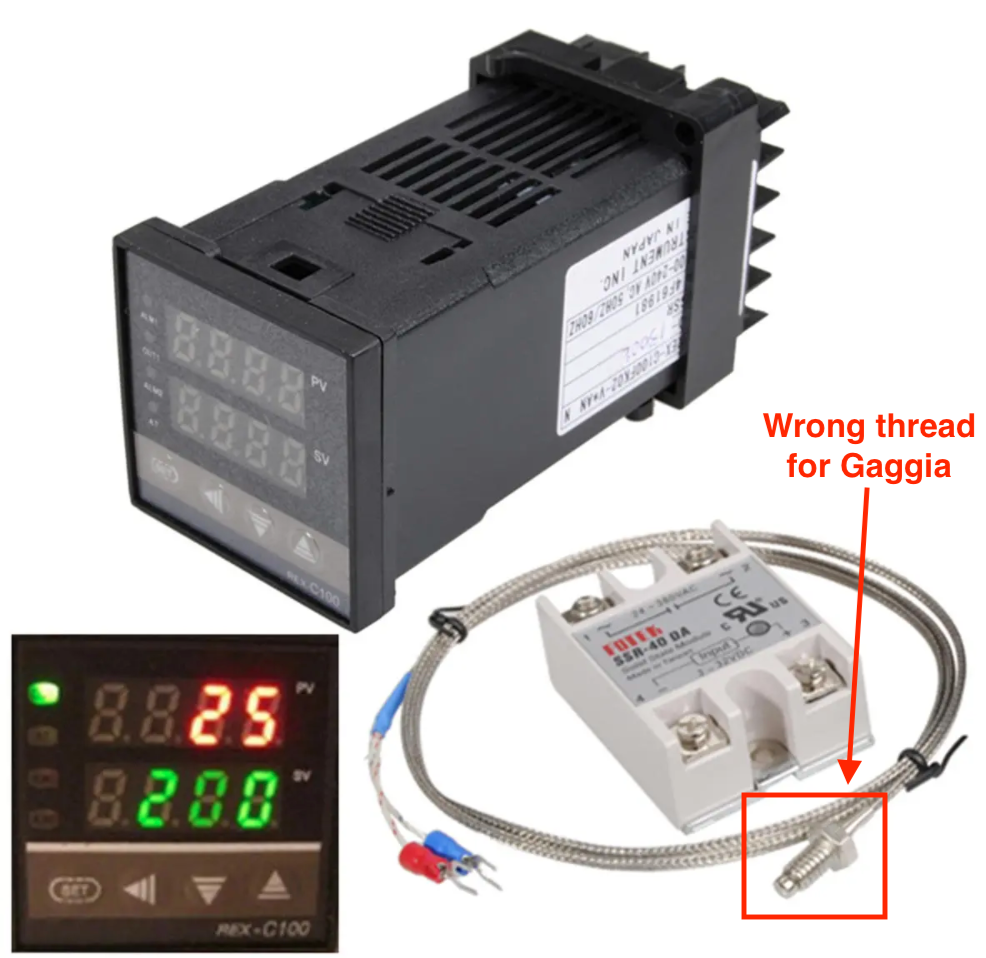
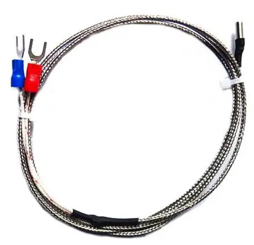
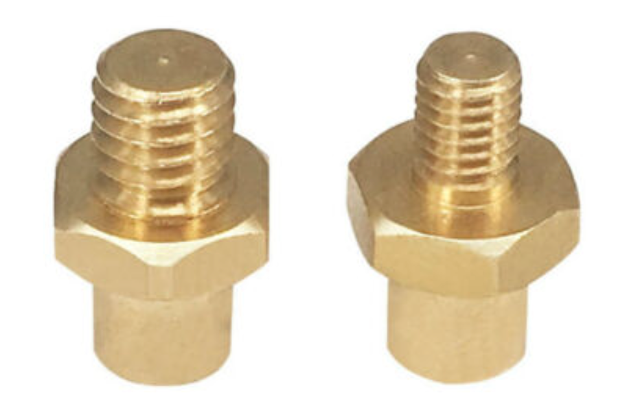
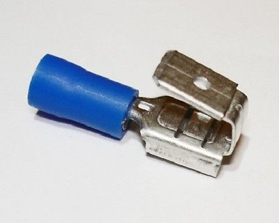
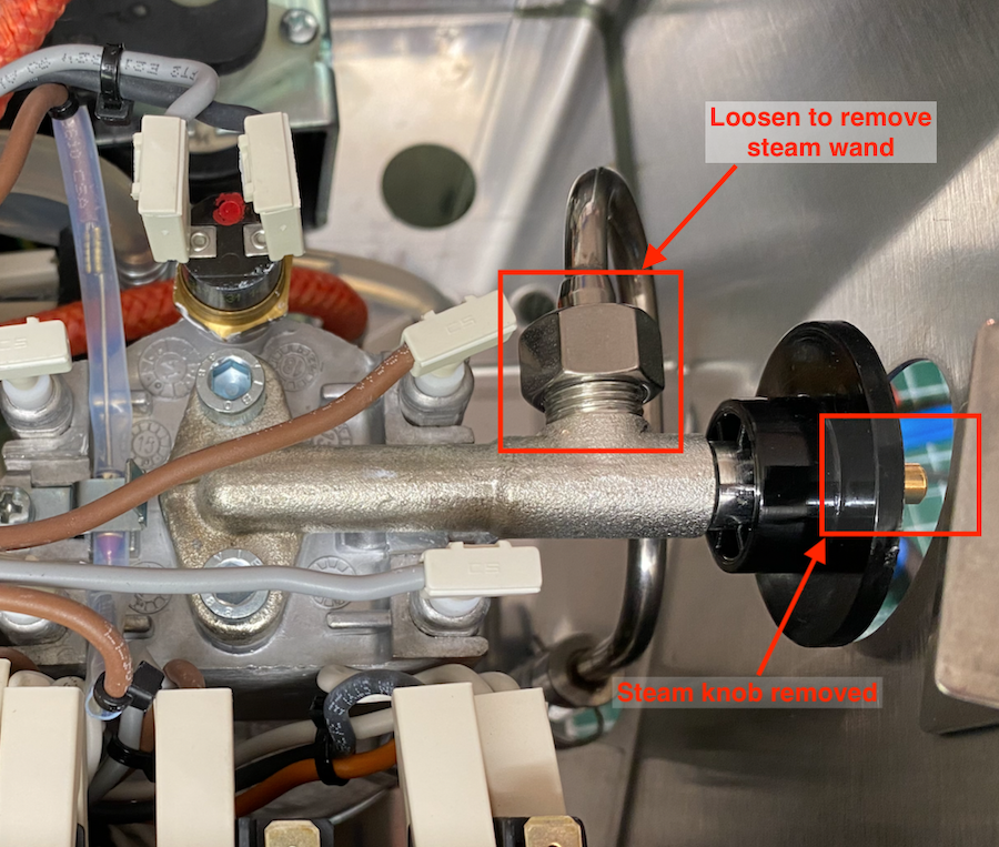
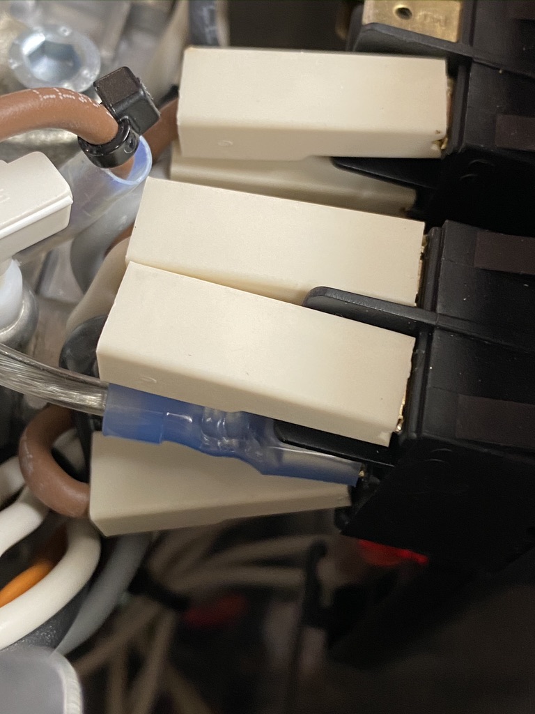
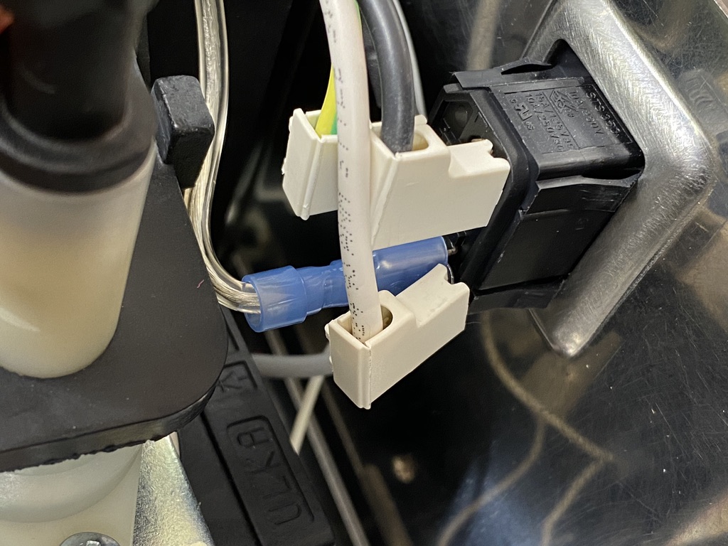
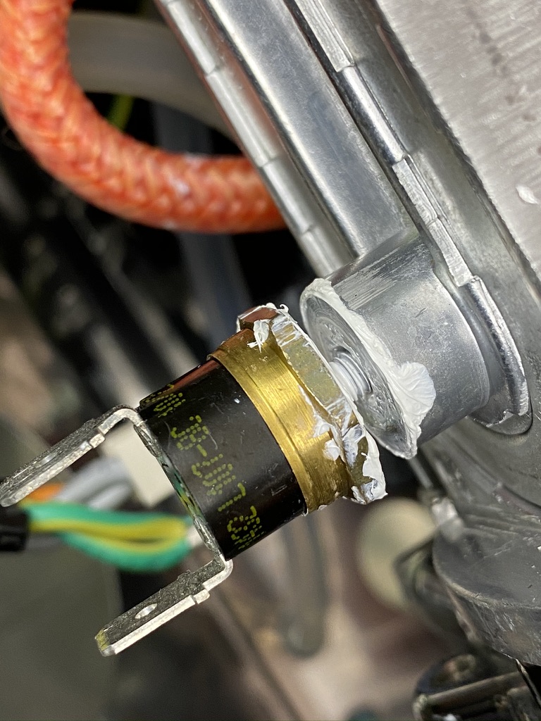
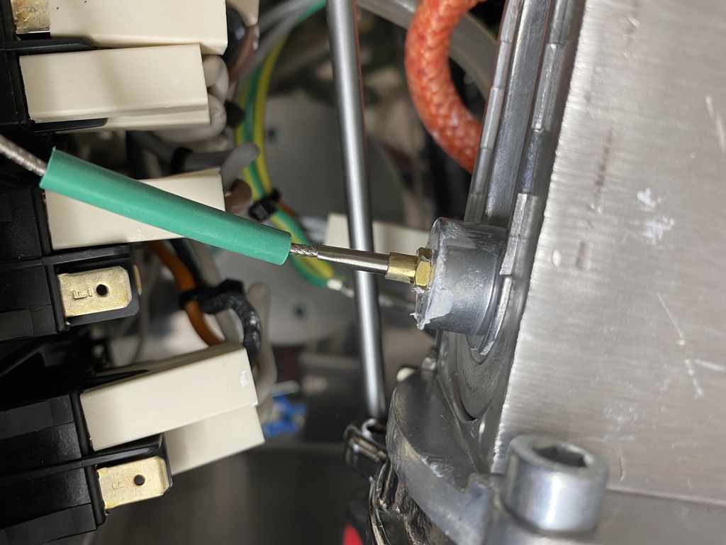
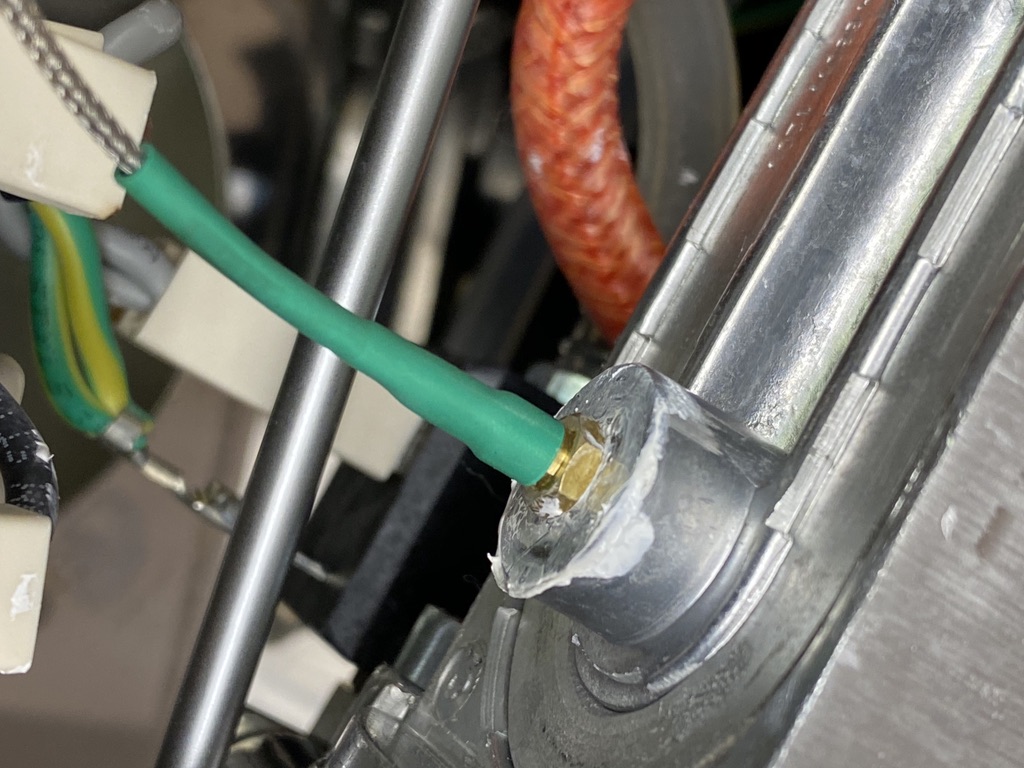
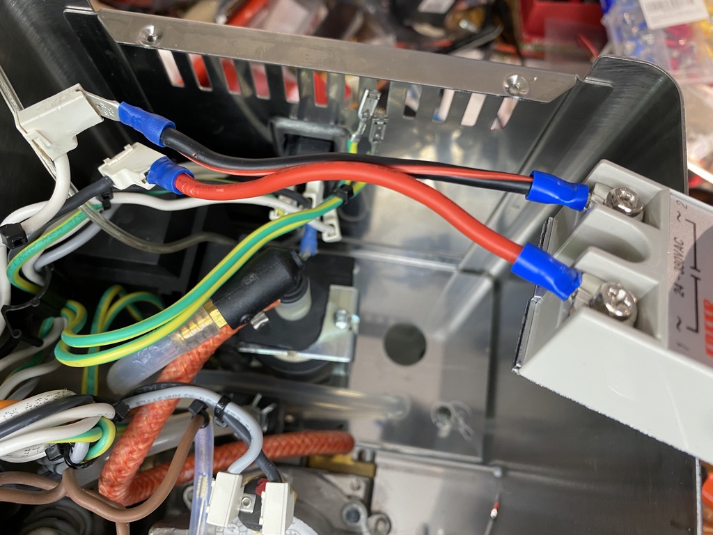
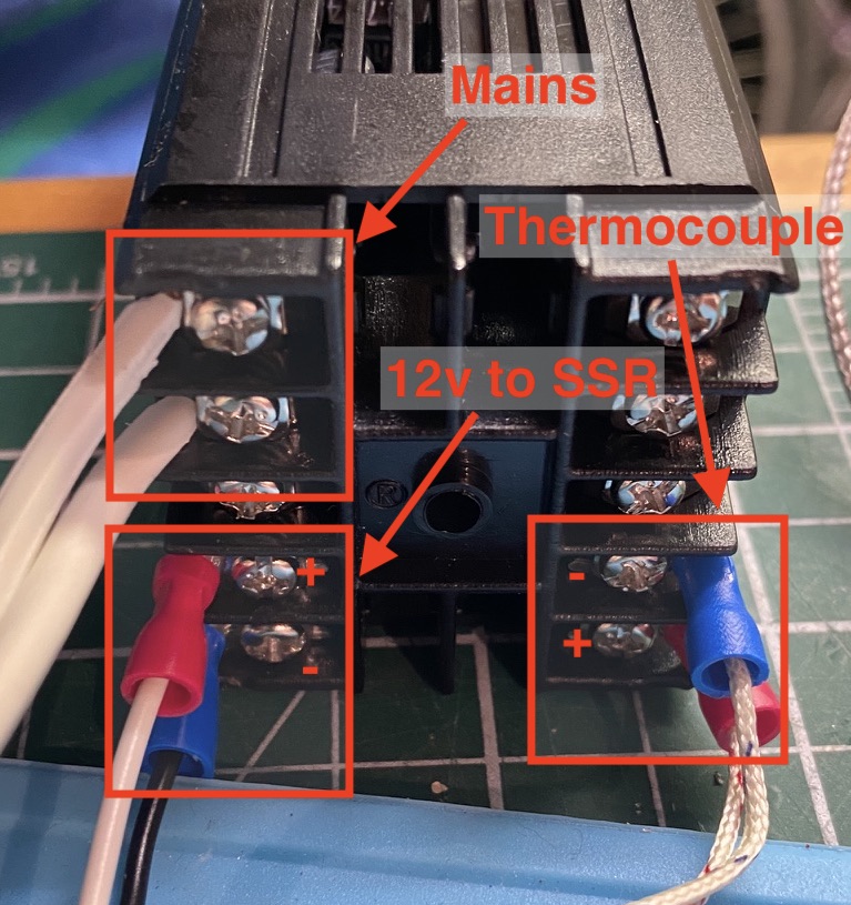
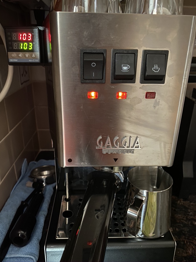
Hey Chris,
Thanks heaps for the detailed instructions. I plan to do this shortly for my old gaggia classic. Would you be able to post starting values for the PID kit please?
I’ve been reading up many different values for the P, I and D, and i’m not sure where to start.
Cheers.
Hi Nish. I have not changed any of the P, I or D settings on my controller. The factory settings have been working well for me, aside from a ~5 degree C overshoot when it first reaches the target temperature. Once warmed up, the recovery time is quick and the swing is fairly minimal. Maybe I’m missing something?
Nevertheless, I will take a look and see what values my controller is set to.
Hi Chris, I’ve followed these instructions exactly (thank you for your thoroughness) except for how the mains were tapped: I moved the two wires terminating on the bottom of the power switch to the top, and tapped them (as per another guide…)
I’m running into problems and I don’t know if my REX-C100’s starting values are the problem or if its my deviation with the wiring: Regardless of the temperature that i set on my PID, toggling the Gaggia ‘on’ causes it to climb to 150-160C and then slowly decline to 118-125C, at which time it will heat up again. I’ve noticed that the PID’s ‘output1’ LED isn’t illuminated after it climbs above my set temperature (103) but the boiler is getting heated up regardless. Any ideas? I had to manually enable autotuning on my REX-C100 and i don’t know if other values are screwed up or if its something else, since it really does seem like the boiler is getting power in bypass of whatever the PID is doing.
It looks like your GC is in steam mode. What you describe looks very much like the steam thermostat cycle. Did you reverse any wires to the steam switch? I am not sure exactly what you did when you moved the wires terminating on the bottom of the power switch. Fortunately, no damage done, and you can easily revert your changes.
Thanks for your reply: I think you are correct about the Gc being stuck in steam mode, but I never touched the steam switch’s wires and reverting the top/bottom swap on the power switch didn’t solve the issue. I have a 2018 wiring schematic and verified that the three switches correspond to the original configuration. I’m tempted to return the GC because I never used it prior to the mod and it may have been a pre-existing issue….
There is definitely something weird going on. It would be great to see how the machine is behaving without the PID, to get a baseline.
I’m wondering if this could somehow be the outcome of a bad SSR: I’m not seeing current flow between the two AC terminals of the SSR when the PID is attempting to heat the boiler to the Set Temp. The LED on the SSR is functioning but no current can be seen. Even if that is the case, i don’t have a clue as to why i would be in steam mode, since i didn’t touch the steam mode button or its wires, i have already reverted my swap of the power switches wires (just from up to down on the same switch so that shouldnt have impacted anything) and i’ve validated that the rollback was correct with a multimeter. I also checked to ensure that the physical steam switch is functioning correctly and the circuit is broken when it is off.
I’ve attached an album with my wiring below; I’ve literally had an engineer look at it and The Gaggia is 100% at its original state except for the power taps on the neutral at the plug, the live on the brew switch, and the thermocouple to SSR wiring: https://imgur.com/a/rc4xtfz
Your wiring looks right. I am going into speculation mode here… I wonder if your Gaggia came with the steam and brew thermostat positions reversed? That would be easy enough to verify with a multimeter, to see which thermostat is active in steam mode and which one is active in brew mode.
The SSR is just a fancy switch and it should only be turning on and off, so depending on how you measure you may not see current. You can verify the SSR by disconnecting its AC terminals and checking that it is indeed turning on and off.
CONCLUSION! The boiler had been installed in such a way that it had pinched/nearly severed the upstream wire on the brew light. It was impossible to see without getting down into the wire harness. Replacing that wire= everything works perfectly now!
Awesome! Glad things worked out.
Hi Peter. The C100 is probably made by dozens of different manufacturers. Always double-check your specific model’s wiring terminal layout and numbering scheme. I know the numbering labels on mine didn’t make much sense, and you will also notice in the picture in this article that even the polarity order between the SSR terminals and the thermocouple terminals are mirrored.
As for your PID always remaining on, it looks like you wired it to the unswitched mains, instead of the switched power. You should be able to find the switched mains with the help of a multimeter. You want to connect the PID’s mains power terminal to the side of the Gaggia power switch that cuts out power when the machine is off. If you used piggyback connectors, it should be a quick job to move the right one over to the correct switch terminal.
Hey. You said here that the to get an M3 thread for the boiler. Everything else (Auber and Mr Shades) includes an M4 thread on their pt100.
Is this a typo on your part or a mistake on their part? That is confusing.
Hi Andrue. You are right, it’s an M4 thread, not M3. The listing shows both M3 and M4 options, and I typed the first one when I wrote the article. Thanks for the catch, I will correct the article.
Is it possible to do this with the GC factory temp sensor?
Also really awesome write up. Thank you for making it.
Hi Ray. Unfortunately, no, you can’t use the factory sensor. The GC comes from the factory with a simple thermostat that turns on at a certain pre-set temperature, and turns off at another pre-set temperature. It’s not a sensor, it doesn’t send any information, it just switches on an off, at setpoints that you can’t adjust. If you go for a PID, you need to use a thermocouple.
Well I ordered the wrong thread. In the text it says M4, but on the picture, it highlights to use the M3…
I’m sorry about that, Eric. The image I used is wrong and confusing, and I have now updated it. Somebody else (Andrue) had also pointed this error out.
Hi Justin. I am flattered, but will have to pass. This is really a DIY project. It will void your warranty, the possibility for making errors or breaking things during installation is too high, and the amount of time it takes would make it cost prohibitive.
If you’re not comfortable installing this yourself, and taking on any followup maintenance, I think you would be much better off purchasing a machine that comes with a PID from the factory.
Hey Chris, I’m wanting to put the pid into an extended 3d printed driptray. If you had to recommend a single display PID, which one would you steer me to? Thanks in advance, this was a huge help!
I actually ended up getting the one you recommended. Is there an easy way to set a brewing and steam temp?
Hi Miguel. The C-100 can accommodate only one sensor/SSR, so you would only set it for brew temperature. You can use the sensor reading on the PID display to know when to start steaming. The PID will be more or less bypassed when the steam switch is on, it will just stop trying to heat because the boiler will be over the PID’s target temperature.
Otherwise, as I said in instructions above, to set the brew temperature, press the ‘Set’ button on the front of the panel. Then use the left/right buttons to select the digits to increase and decrease, and the up/down buttons to change the digits. It’s pretty straightforward.
Brilliant article.
Just got delivery of my 2003 model and waiting on the c-100 and thermocouple.
Does the wiring you’ve supplied automatically shut the PID unit off when you engage the steam switch?
Hi Paul. The way I wired the PID leaves it powered on as long as the main power switch is on. When the steam switch is on, the PID stays on but because the boiler temperature in steam mode is much higher than the brew temperature of the PID, the PID provides no power to the SSR and heating element.
While the steam switch is engaged, the PID serves to provide a temperature reading of the boiler, which is great, because you can use that temperature reading to time when to start steaming for maximum steam performance.
Hi , I followed the instructions but the PID starts up with some number and it doesn’t look normal , LCD just keep blinking some numbers the goes of for a few seconds the I get some numbers for half a second, it’so quick I can’t tell what is displaying, could I have got the power wiring wrong or if the cable are higher AWG would it causes issue?
Hi Kez. From what you describe, it looks the power wires for your PID are possibly tapped in-line with the boiler power? This would explain the constant switching on and off. Try powering the PID directly from mains power, with just the thermocouple connected (disconnect the SSR). You should see a strange number when the PID first powers on, then after about 3-5 seconds it should switch to the temperature reading from the thermocouple. If the PID stays on when wired directly to mains power, you will need to figure out which power wire to tap into. It should be the power/mains line that comes out of the main power switch, but before the boiler.
So the above instructions might not apply to the UK, I have the GC2019 but the live connection was the top right on the power switch when switched on, bottom left caused the PID to flicker and not work as expected, I fixed my issue but now the PID readout is 103 Dec but the water is 80 degrees, didn’t think it would be off by this much. Is there a way to calibrate the read out close to the water out temperature
Feedback is that there are almost no two GCs with identical wiring, even units destined for the same power rating. Wire colors and positions seem to vary. Glad you got that sorted out.
I would be surprised if your water is 80 degrees coming out of the boiler with the PID set to 103, but it’s possible, depending on the thermocouple you’re using. This video clearly shows how to program in an offset on the Rex C-100: https://youtu.be/9aW8MfiKIPg?t=291.
Hi chris,
I bought the same parts as you have reccomended in the article but have run into the issue that the thermocouple is too large to fit into the adapter (they’re approx the same OD). Did you have to alter your thermocouple at all to get it to fit into the adapter, like removing the cap on the end or something?
Hi Evan. The PID I ordered came as a package with a solid state relay and a thermocouple, but that thermocouple had too big a diameter to with the Gaggia. The thermocouple that I ordered fit into the threaded adapter without any modifications. You could definitely drill out the adapter a bit to get the thermocouple to fit. Brass is soft and easy to drill, and all the adapter needs to do is provide a connection between the thermocouple and the boiler, so there would be no hard in doing this.
Hello.
I am thinking to upgrade my classic pro more compact version with below controller.
Will it work or not?
QB-T7200 48*24mm Programmable Digital PID Temperature Controller with Built-in 5A Solid State Relay XMT7100 AC/DC85~260V
https://a.aliexpress.com/_m0zEvdH
Hi Eddie. That controller is an interesting find. You’re giving up one of the two temperature readouts, so you’ll probably only see the actual temperature, as opposed to the target temperature, and I guess you can switch between the two with a button press.
It should work as a replacement for the C-100 and SSR, but because the SSR is built into the PID, so your wiring will be a bit different. This PID-SSR combination does away with the 12v connection, and uses three wires for the mains power and SSR, with one wire shared between mains and the SSR output. You would need to put the boiler heater element between the controller terminals 2 and 3. But I would definitely read the instructions that come with whatever you receive!
Hi Eddie. I have re-read the specifications for this controller. The SSR is only rated for 5 amps. This won’t be enough for the boiler heating element. You need at least 20 amps. You would probably blow the fuse in this controller/SSR within seconds.
I think this is why using a separate SSR and controller is the only way to go. At the amperages required to control the boiler heating element, you need an SSR that has enough mass and exposed metal to be able to attach it to a heat sink.
Hello, there is another model without SSR built in with name 7100 instead of 7200. I think one of either is the one which Shades of Coffee is using.
By the way there are three options as 12V, 24V and 85-250V DC. Which one shall we buy? Thanks
Hi Murat. You need a 85-250V DC model, as the power will be coming from the Classic, which is mains-level voltage.
Due to your kind and quick advice, I could order SSR40DA.
Thanks a lot.
Hello, thanks for the nice and valuable text. Mr Shades is selling many small items (piggyback, spade, thermal paste, power cable, rubber grommet etc.) under the name “replacement PID kit parts” with very low prices. I will purchase the PID kit with thermocouple and SSR from aliexpress and buy these rest small items from Mr. Shades. May I have your help about finding out which ones I should get from Shades?
Hi Murat. It would be almost impossible for me to give you a complete list of the parts from Mr Shades that you will need, as it will depend on the PID and SSR models you order. Most likely they will have the same connector types as the REX-C100, but it’s always possible that you will need different connectors depending on what you end up ordering.
At a minimum, I think you would need the following:
I don’t see piggyback connectors on Mr Shades’ list, maybe those are part of the set of wires, but it’s not clear.
Thanks a lot for the answer.
I have found the exact PID unit which Mr Shades is using and purchased it beside the Rex C100 kit you mentioned above:
QB-T7100 48*24mm Programmable Digital PID Temperature Controller AC/DC 85-250V
Unlike the 7200 model, this one does not have SSR inside. My plan is to install the Rex C100 first using your instructions. Maybe then try QB-T7100 afterwards and if it works I will buy the external case which is sold seperately (QB looks nicer with small size and external case). My only concern is that Mr Shades has two types of SSR units 40AA and 40DA. Do you think this makes difference? Or do you think the same set will work with QB-T7100?
Hi Murat!
I plan on doing the same thing as you did, bought both PID simply because the QB-T7100 is slimmer the case is readily accessible from mr. shades, compared to the higher cost of 3d printing a case for the REX.
I wondered if you ended up testing both in the end. Did you have any problems or stumbled upon anything unexpected? Did you try with the SSR unit 40 DA or 40AA?
Thank you very much if you find the time to answer me 🙂
Shades uses an XMT7100 modified to run two SSR’s: a DA for the brew temp and an AA for the steam temp. You can mod the XMT7100 yourself but it requires soldering on the PCB, basically removing the onboard relay and then jumpering the empty terminals. It’s not hard if you know what you are doing and there is at least one youtube vid showing how it’s done.
The same can be done with the REX C100 but you need one with all 8 screw terminals (the second SSR for steam uses the alarm function which needs terminals #6 and #7) and these two are missing on some REX’s.
Perhaps you are refering to the video by Damian Witonski. that will make it where only one SSR is needed. different wiring though. however the one SSR is nice and the modification gives upgraded steam with the solder mod.
On thing I realised is that Mr Shades does not allow purchasing the parts seperately unless you already purchased the kit as a whole. You can only buy them as spare parts.
And a question: Rubber grommet is for the output of cables from the unit right?
Thanks
I am not surprised, Mr Shades runs an honest business, and those parts are being offered at low prices. I deliberately avoided looking at the Mr Shades kits and instructions when I wrote this article, I don’t want to steer people away from them. Their kit is convenient, and is the way to go if someone doesn’t feel ready to take on a 100% DIY project. The grommet is used where the wires go through the chassis. I did not use a grommet.
Hello, I acquired and prepared all cables and SSR unit thanks to your well prepared title above. I am now waiting for my PID unit and thermocouple with M4 head to arrive this week. I have installed the supply cable for PID unit using piggyback spade connectors. I tested the current with multimeter and it is showing DC 100V when I turn on the on-off switch. When I turn off, it goes back to zero. Does this mean that I have made the connection properly? One end is connected to the mains connector at the back (where it is showing N sign), the other end is connected to the back of the on off switch (as you showed on the picture above).
My only concern is the diagramm I downloaded from whole latte love shows different connections then what I have seen in my unit
https://wiki.wholelattelove.com/File:GAGGIA_CLASSIC_2019_Wiring_Schematic.pdf
It shows that neutral cables coming from thermostats are connecting each other under the steam switch but mine are connected under the main switch. Do you think this makes a difference? Shall I connect it to terminal 5 or 2 of the on-off switch? (I believe it is currently on 5) Or shall I just keep it as it is, showing DC 100V when I turn the switch on?
One last question: Auber and Mr Shades are calling their sensors PT100 while mine is K type thermocouple. Do you think this makes difference? Thank you.
Hello again, I found out that connection I made was wrong. The PID unit did not turn on using the same terminal of your machine. In mine, correct terminal was crosswise of yours. The best way to find is: 1-Connect one cable to the mains connector at the back where it is showing N sign – meaning Neutral. (Markings can be found on front side of the plug) 2-Check the color of the cable which shows L sign on the plug- meaning Live. 3-Connect the other cable to the terminal on the on off switch, which is on top of or below the Live cable. This is because the switch is connecting the terminals vertically when it is turned on.
I am glad you solved the problem, Murat. I am beginning to suspect that Gaggia created as many combinations of wiring configurations and colors as they made machines. It’s crazy. I’m all for freedom of expression and creativity, but not when it might electrocute someone.
Hello Chry,
Thanks for sharing this awesome guide.
One question, Ever thought about adding a pre infusion feature? If so, any idea how it can be achieved? Pressure control could be super nice to have.
Thanks
Hi Nitzan. I have briefly thought about pre-infusion but the REX C-100 is not capable of this. Adding pre-infusion would require either a different and significantly more sophisticated PID, or integration with something like a microcontroller. Either way, you are looking at a lot more complexity and cost. You could simulate pre infusion by briefly running the pump.
The same complexity applies to pressure control. If you really want these features, it’s probably time to think about upgrading your machine.
Whole Latte Love has a new video about preinfusion on the classic. Basically, instead of running the pump for a few seconds and then shutting it off (which dumps your pressure courtesy of the solenoid valve) you open the steam valve about 1/4 to half way, hit the brew switch and then slowly close the steam valve (about 5 seconds or so). This way you are not losing any pressure via the solenoid valve, you are just reducing the initial pressure to the puck by venting some of it through the steam wand.
https://www.youtube.com/watch?v=AoZuYaDq5yc
Thanks Jeff, that’s a great video. I know what I will be trying tomorrow 🙂
Hi,
The Rex c-100 reads in Celsius only, would I be able to substitute this kit with:
(PID Temperature Controller Meter Indicator, Jaybva Digital Universal Thermostat C and Fahrenhe F Display SSR and Alarm Output 40A Solid State Relay and Thermocouple Probe Heat Sink Included)? This is sold on amazon
Specifications :
Power supply : 90-265V AC/DC
40A SSR Solid state relay included
Mounting Dimension: DIN: 1/16 (48mmX48mmX80mm)
Thermocouple included: M6*1 thread , K type , 2m cable
Display: Dual display for Fahrenheit(F) and Celsius(C)
Range: -1999 to 9999 (depends on the input signal)
Main Output: SSR: Open circuit: 4V, Closed Circuit: 24V40mA DC
Auto-tuning PID cooling/heating control
1 RELAY alarm: Normal open, capacity 250V/3A AC or 30V/3A DC
Accuracy: 0.2%
Universal Input: Thermo Resistor: PT100, Cu50 . Thermocouple: J,S,K,E,Wre3 ~ Wre25
Net Weight: about 150g
Individually PID control parameters
P, I, d, controlling period, digital filter coefficient, and more… (for control theory experts only)
SSR control ready to connect external Solid State Relay to handle High current. Applications
K type thermocouple, 0-500℃, 2m cable (6 feet).
Thanks for your time
Hi Brian. The PID kit you described should work, but like the C-100 kit the I used, the included thermocouple won’t fit in the Gaggia Classic. Note that according to this video: https://www.youtube.com/watch?v=UETVv0qgz-w, you can switch the C-100 between Celsius and Fahrenheit.
Hey Chris,
great article !!!! Is it necessary to use a heat sink with the SSR installation?
Thanks for your time
Hi Brian. Most guides recommend connecting the SSR to the Gaggia’s (metal) body with some thermal paste, and this mount then serves as a heat sink. So I would say yes, you should use a heat sink, but the Gaggia body conveniently provides you with that function.
Hello Chris,
I managed the brew side PID and digging in for the steaming side, using PID alarm function of my XMT 7100 unit. I purchased an AC to AC SSR (SSR 40AA) which will stabilise steaming temperatures in much smaller margins than the original steam thermostat. However I now need to connect steaming and brewing circuits in parallel rather than serial because steaming circuit will not be closed unless I turn on steaming switch and supply power to steaming SSR. Thus brewing circuit needs to be connected directly to the heating element, not over steaming circuit.
My problem is, unlike Rancilio Sylvia, heating element of Gaggia Classic Pro seems impossible to connect without cutting cables. I don’t want to void my warranty. Do you know how to do this? I think Mr Shades has managed to do this using only cables because I don’t think he instructs anything to void the warranty. Do you have any idea how to do? Thanks.
Hello Chris,
Awesome guide! Thanks for putting it together, this has helped me a lot in figuring out most of my doubts with a PID project for a Gaggia. I still have one question you may be able to answer.
My Gaggia Classic uses 18 awg wire for every connection inside. I’m assuming it should be fine as well to use 18 awg wire to wire the mains connections to the PID, and between the heating element and the SSR?
Between SSR and PID I was planning on using 22 awg wire given its a lower power requirement.
Thanks in advance!
Hi Jun, glad you found this helpful. You can use the same 18 gauge wire between the heating element and the SSR. You can get away with lighter gauge wire for the mains connection to the PID, as the PID draws very little current. I used lamp cord for this. The PID is really converting the mains voltage to 12VDC both for its internal operation and to drive the SSR, so the PID’s draw is quite small. Likewise, you can use 22 awg for the connection between the PID and the SSR.
Hi Chris, I appreciate your tutorials on the PID install. My question is where did you place the SSR, is it near the water spout, right side or in the back if you are facing the front of the machine? Thanks!
Hello Chris,
Awesome PID installation guide!
Where did you place the SSR? Left or right side if facing the front of the machine?
Thanks, David
Hi David. I placed the SSR toward the left side of the back panel if facing the front of the machine.
Thanks, I see what you mean. It is the perfect place.
Hi Chris,
I just installed the pid on my Gaggia classic Pro following your instruction guide. I have a question on the pid, it is normal for the brew light to blink (off and) while it stabilizes to the target temperature. Thanks, David
Yes it is normal for the brew light to blink like this after you install a PID. The PID switches the power to the boiler heating element on and off a lot more frequently than the original mechanical thermostat.
Perfect, came back here to ask this question! My install went as smooth as I hoped… all my wire colours and locations were identical to yours (Phewf). I found that moving the boiler up and to the side allowed me to get to the thermostat from the bottom really easily vs. the top. Thanks again for the write up, I’ll be playing around with temperature for the next week!
Hi Miguel. I am glad this article helped. I hope you enjoy your upgraded GC as much as I do mine!
Hi Chris,
Is 103 degree Celsius the best target temperature fit the PID? Thanks
Hi David. I started with 103, and bumped it up to 105. It will depend on the beans you use, and your palate. My experience, and that of others including a commenter on this article, is that I would not want to go lower than 103 on the Gaggia Classic. The 103 is not a true 103, that is what is getting measured in the boiler wall, and there is also a temperature drop off between the boiler and the portafilter, so your final espresso temperature will be lower.
The fun of the PID is not just the great stability, but the ability to fine tune the brew temperature to your taste!
You can take a look at this discussion about offset in the Gaggia Classic: https://coffeeforums.co.uk/topic/53319-what-temp-offset-are-you-using-with-your-pid/
I don’t bother with offset, once I have a temperature dialed in, it doesn’t matter whether it’s measured at the boiler or offset for the group head.
it does not matter if the bean is dark or light roast? What is your coffee bean dark or light? 103 or 105 is good.
I use 103-105, with dark roast.
Does this pid control both the group head water and steam wand?
This PID only controls the group head.
When the PID signals the SSR, as indicated by the brew ready light and the output led on the PID, the pressure coming out of the pump decreases, and then increases again after the PID out to the SSR turns off. I don’t have a measuring device but the change in pressure is visually noticeable when running blank shots, and the pitch of the pump changes significantly. The pump is not wired in series with the Heating element so I’m not sure what is causing this. I haven’t lowered brew pressure to 9 Bars yet so perhaps changing that would level out my pump pressures?
MY GC does the same thing, the pump tone changes when the boiler is heating. I am guessing that it’s caused by the current draw of the boiler heater.
I decided that for me, it’s not worth worrying about. I like the quality of the shots, and temperature consistency is more important – to me – than pressure consistency. If you really want to avoid the heating element switching while you’re pulling a shot, you can blip the steam switch for a few seconds before brewing and that will bring the boiler temperature up a few degrees. Then the PID will only switch on when the boiler temperature drops below the target temperature.
This steam blipping is a fairly common practice that people use to avoid boiler heater cycling, it’s just another way to do temperature surfing.
Hi Chris, thanks for the reply. I was initially concerned about my wiring (and my GFI) but it’s reassuring to hear you have the same side effects.
Perhaps I’ll use a spare Arduino or FPGA to PWM the boiler while brewing as someone else was saying.
Hey Chris,
Have you checked the temperature accuracy of your PID & Thermocouple? Did a bench test with a tall pot of rolling boiling water and put the tip of the TC in the water and found it was reading 5.5 degrees low. I adjusted the calibration offset on the PID +5.5 degrees to read 212 degrees.Have you any suggestions of more accurately calibrating the PID and TC? I think this would be the most important parameter of the build, obtaining the correct temp of the water. Let me know your thoughts !!!
Thanks again for your time,Brian
Hi Brian. Most thermocouple calibration articles that I have read use ice water to calibrate to zero degrees C because the boiling point of water varies with altitude. Even with a perfect offset, you would also need to also take into account the temperature offset between the boiler and the portafilter. I have read reports of measurements of up to 8 degrees C lower at the portafilter. All of this really means that you should balance whatever temperature you end up reading against what you’re tasting, because that’s what matters in the end. The PID gives you consistency. All other variables aside, once you get a temperature that gives you the results you want, you will be able to get those results again, and again.
Hi Chris, I completed the whole project both for brewing for PID and steaming via alarm. Thanks again for all your support.
I used the same controller ( XMT 7100 ) which Mr Shades is selling. I do not suggest autotuning for this device because there is a huge improvement in temperature stability if you do the tuning by yourself. I used P:2,4 – I:40 – D:10 and Souf:0.2 which gives a shot stability around 2 degrees for single, 4 degrees for double shots. Autotuning had resulted in shot instability up to 10 degrees during a shot probably because conditions during standby and during brewing are very different than each other.
The only suprise for me has been that installing steam kit did not help me much because brewing kit alone helped to have great steaming power by only watching temperature climb up to 150 degrees. When I started steaming at that point thermostat never shut down the boiler because temperature did not reach to limit of thermostat. However with the new steaming alarm system, I get a decrease around 10 degrees in steaming temperature as soon as AA SSR shuts down the boiler at the temperature I set, even it turns on right away (my setting is AL:156 – AH:155 degrees Celcius). I would be glad if you have any recommendations. This is the only concern left for me.
Anyway, thank you Chris. I would not make it without you.
I am glad you got your setup working Murat. I am not surprised that the steam kit made little difference. Once you are able use the PID temperature readout to determine exactly what the steam cycle is, you know when to start steaming for more or less endless steam. For me I start steaming when the boiler temperature reads 130 degrees C.
So for others who are contemplating going for the extra effort of installing the steam PID, know that the return on investment of doing this is questionable, if not net negative.
Hi Murat,
I have few questions for you about this setup.
Do you have any diagram of the wiringi can’t understand how to switch on the steam circuit so the second SSR would not try to heat the boiler in parallel.
I’m on [email protected]
Thanks
This was such a great guide. Thanks.
The YouTube video from wll about replacing the boiler made the whole thing very easy. Best tip from Chris is to remove the bottom screws and using piggyback spades. I bought the PiD from Amazon referenced in a comment above and it’s working fine. There’s also a M4 connected thermocouple wire on Amazon that arrived fast although it increased the whole cost compared to Bangood.
One thing I would really recommend when anyone installs a PID system into the Gaggia Classic is to install a rubber grommet where the cables exit the machine. It’s no secret that the chassis of the Classic has extremely sharp edges. When the pump runs, it vibrates the chassis and it will be a matter of time before it cuts through the wiring insulation. Guys, there is mains voltage here. We have an earth leakage wiring system in our house, but in many countries, these are not standard. The idea of the chassis becoming live doesn’t bear thinking about. Please be sensible and install a grommet anyway!
What size grommet did folks use?
Hi Chris
Great guide. I’m so thankful for this. Please let us know if there’s a way to show our gratitude if there’s a charity or cause we can donate to for you putting this guide together.
One bit of note and a request.
Regarding the M4 screw/ thermocouple, is it possible to amend the picture? It is still showing the M4 screw as the Crossed out/wrong one, and can be a bit confusing. (To be certain, the M4 is the correct one)
Same with the adapter screw.
Might be easier for most folks to buy an M4 screw, type K, thermocouple direct vs trying to get the probe version then another adapter.
Thanks again.
Hi Chris,
Thanks for the great guide.
I have a 2013 Gaggia Classic. Are the steps here suitable for older machines like mine? I know wiring might be different colours but is everything in the same place?
Thanks!
Hi Tom. This guide should generally also apply to the 2013 GC, but you must assume that any of the switch wiring that I describe will be different for your model year. It seems the wiring varies even within model years, and between model regions. Just use a multimeter to find the switched mains, and you should be able to follow the thermostat wires. I also think that you may have less difficulty reaching the thermostat, the 2019+ models have a lot less room to spare inside.
Did you try it? I have a 2012 and am wondering if you had success and if the wires are as described in the article. I don’t own a multimeter.
Chris – thank you so much. I stumbled onto this before I actually had my Gaggia in hand and went about ordering all the parts. 3 months later, I’ve finally set up the PID and honestly, it’s a gamechanger!
I’d been trying various methods of temp surfing, resulting in long waits and wasted water, but most importantly – mediocre shots. I have only been drinking milk drinks and americanos because the shots I was pulling were always overly bitter, sour, or both, regardless of grind and quantity.
This morning I pulled my first shot with the PID. Bliss. No gross taste. I can actually taste the sweetness for the first time. Thank you again for taking the time to write up such a great guide.
Thanks Alex! I agree, the PID is a gamechanger. The lack of consistency pre-PID is frustrating, because you can get everything else right and still be at the mercy of the temperature determined by the thermostat cycle.
Hi Chris
I have found this PID kit here on Ali express and I think it’s the same one you fitted can you please tell me if this one is good to go, they got a 3 piece option and a 4 piece option so don’t know which, I think the 4 piece option is because it includes a heat sink that you don’t mention, so I assume I won’t be needing it, can you please advise.
Thank you
https://www.aliexpress.com/item/32975122837.html?spm=a2g0s.8937460.0.0.11b02e0edh0ELd
Hi Joe. The kit looks a lot like the one I ordered. You won’t need the heat sink, the GC’s case does that job for you.
But just like the kit I ordered, the threads on the thermocouple – M8 according to the specifications – are too big for the Gaggia.
I found this M8 female to M4 male reducer: https://www.ebay.com/itm/284317077676. Maybe this could serve instead of trying to find an M4 thermocouple.
did the REX-100 require most of the default setting to be changed or is it similar to changing like shades PID or Auber PID
Hi Jeff. The C-100 that I received was set up properly, I only had to change the temperature. They are easy to unlock to get to all of the other settings, there are plenty of instructions on how to do this out there, but I didn’t really need to go there.
How do I ensure that I’m tapping the “neutral mains”? What exactly is a mains-rated wire, and where would I find one? I’m in North America btw.
If you are in the U.S. then mains voltage is 120V, which will not kill you (unless you have a pacemaker or are standing in a bathtub) but can give you a decent shock. But follow chris’s advice and be careful and you should be OK. And also use a rubber grommet to route your wires through the slots in the back of the chassis. Even though the wires are insulated, as someone posted earlier, that metal is sharp and the vibration from the machine may eventually cause the insulation to fail and then your whole machine is a conductor. You can buy them at Ace hardware for about twenty five cents each.
Hi Rusty. Mains is house current. The PID itself draws very little current, so something like 18 gauge lamp cord would work. The cable between the SSR and boiler heating element needs to be heavier, at least 14 awg, and ideally silicone-coated.
Neutral is the return path for the hot or load wire. In a properly wired North American outlet, the neutral wire is white, and the hot/load wire is black (ground is green). Inside the GC, all bets are off as to wire colors, aside from green for ground, and even then, I wouldn’t assume anything.
To find the neutral inside the GC, you have to test using a multimeter or voltage meter. If you have never done this before, know that you are working with live household current, and this can kill you. If in doubt, sit it out, and get some help. Connect one meter probe to ground (the GC chassis should always be grounded, otherwise connect to the green wire coming from the power socket at the back). Use the other probe to check the other two wires coming from the power socket. You should see no or very low voltage between neutral and ground, and you should see household voltage between the hot/load and ground.
This guide explains this well, and also explains what to do if your home wiring is not correct: https://diy.stackexchange.com/questions/195229/in-a-light-switch-how-can-i-tell-if-the-black-wire-is-really-hot-and-the-white
Hi Chris, i noticed you used the K type thermocouple with the M4. i heard from some that the PT100 with the M4 is more accurate. have you had any issues with the k type or have heard of this? i ordered K type and PT100 both for M4.
I went with an insulated PT100. That’s what Auber and Shades use, although they make their own. Supposed to be faster in detecting temperature changes and more accurate with the measurement. Never used a K type so I can’t say for sure. You’re probably fine with either one.
Have you noticed any problem using REX-C100FK02 and RTD PT100? This is the setup that I have assembled two days ago…
Chris, i read some comments here about steam. if i understood not adding a steam will give better steam? But will there be an upper limit to prevent the boiler from going near 365F and blowing thermal. Both shades and auber use the alarm 1 & 2 though with different PIDs for steam with upper limit & lower limit. it appears i can configure the BERM REXC-100 like this as i entered the settings after i enabled alarm 1. auber uses 1 SSR & is simple. shades uses 2 connecting one ssr thru the other for steam. i’m trying to find out from shades why shades uses 2. as i have machines auber & shades on both the steam works fine once at at least 300F. i set an upper an lower limit on alarms. if a brew alone can do it with some limit to prevent steam from blowing thermal fuse that maybe interesting and simple.
Hi Jeff. I had no issues with the K type thermocouple. Regardless of which thermocouple you choose to use, you will also need to factor in an offset no matter what thermocouple you use, and this is really based on your tastes. And anything is going to be a huge improvement over the thermostat that the PID replaces.
As for steam, the guide I wrote leaves the steam function completely untouched. Steam will still be controlled by the steam thermostat. From the factory, the GC has two thermostats, one for brew, which the thermocouple + PID + SSR replaces, and one for steam, which stays untouched.
What you do get from the PID as per this guide in steam mode is the ability to see exactly what the temperature of the boiler is, so you can time your steaming to start during a heating cycle, which essentially gives you unlimited steam.
From what I have read, the PID with the additional steam mode option does not improve things much.
Hi Chris, I am gathering / ordering the parts specified and was surprised to find out the price for 3d printing price spiked. Some shops are quoting $80.00 for the PID enclosure + lid. This prompted me to look for alternate solutions. I was able to create one using Lego bricks sitting around in the basement. Does the PID generate enough heat to melt the Lego bricks?
Hi Jimmy. I love the Lego enclosure idea. If you can share a picture of it, or a link, I can add it to the article.
I print with PLA filament, which has a much lower melting temperature than the plastic that Lego uses. Also, the PID generates almost no heat, because the ‘work’ is done by the SSR, and this is heat-sinked to the Gaggia. So there is more or less no concern about PID heat and the PID enclosure. The enclosure’s purpose is first to protect you from the mains current, and second, to make it easier to attach the PID to the Gaggia.
Hi Chris,
Here are some pictures of the Lego enclosure: https://www.reddit.com/r/espresso/comments/owpfe7/i_made_a_lego_enclosure_for_rex_c100_pid/
Thanks Jimmy. That’s an awesome enclosure.
Chris, do you recall what size flat head screw was used on the 3d printed box for the REX-100?
Chris, this is a far simpler way to add preinfusion. it works better than poor mans preinfusion described by wholelatte love & Lance in the youtube. and its definately better than Auber which is NOT preinfustion by kicking off solenoid. it is basically removing the main pump wire and re routing back to the PWM out. the PWM needs a new wire to the where the pump wire was disconnected. This works well with a PID for light & medium roasts. best part it is inexpensive and as easy as OPV mod
here are the links:
PWM dimmer for preinfusion
https://www.amazon.com/gp/product/B00LODGP2E/ref=ppx_yo_dt_b_asin_image_o05_s00?ie=UTF8&psc=1
BOX
https://www.thingiverse.com/thing:4243840
Hi Jeff. I grabbed some screws from my parts bin, I took whatever I could find that was the same color as my filament, and that would fit the holes and hold reasonably well.
Here’s a picture of the screws I used, with screwdriver for scale:
Great article and development, congrats!
Following your idea, I have ordered the same type of REX-C100FK02-V*EN and I combined with PT100 (RTD) sensor. The PID, RTD sensor and SSR (20 Amps) are installed on Gaggia Classic Pro 2018+. I have changed the default value of the SL parameter to work with the RTD sensor (K thermocouple was default).
I have couple of concerns with this setup and would like to kindly ask for your opinion:
1. Do you think that REX-C100FK02-V*EN (designed for K-type thermocouple) is compatible with RTD (PT100) and is not going to create long-term problems with the machine/setup? The label on REX-C100 says that it is produced by RKC, Japan – but you never know for sure :-). I have noticed after PID installation that upper cup holder tray is getting quite hot during 8-10 min warm-up, which was not the case when I was using the original GCP setup. Is it possible, despite setting the temperature to 102 degrees Celsius as SV, to actually run GCP much hotter due to incompatibility of the PID and RTD? I have to mention that coffee taste is good, not harsh or bitter.
2. I ran the Autotuning function couple of times and I am always getting the following values for P, I and D parameters: P=620 , I=32, D=8. Is P=620 maybe an overkill, as I haven’t seen such a big value at other places?
Shall I change the P,I and D parameters manually and what is your suggestion to start with?
3. What is the intra-shot temperature fluctuation that you are seeing on your machine with your PID setup?
For the sake of piece of mind, I have ordered last night a K type thermocouple in order to replace the RTD P100 and close the open loop in my head about PID type and sensor. Nevertheless, it will take some time to get it and make a change of the temperature sensor.
Looking forward getting your thoughts and ideas…
Thx,
Nikola
I have a similar model, C100-Fk02-V*AN. The ‘A’ vs ‘E’ should not make a difference as I am not using alarm function, and am using it with a 3-wire PT100. Despite the ‘K02’ indicating K-type, it was advertised as supporting multiple types including PT100.
The cup warmer does seem a bit hotter than before (but have only used twice since installing, so I’ll have to pay attention).
After autotuning, my values are:
P – 53.1
I – 37
D – 9
My P value is quite a lot different than yours.
I will monitor it over the next few days, but if the coffee takes good, and the only thing I notice is the warmer cup tray, I’ll be fine with that, better in fact!
My theory at the moment would be that due to the PID control the heater is sometimes on at higher temperatures. With a SV of 103C (not offset), during initial overshoot the heater would sometimes be one when it was at 104-105C with the temperature rising as high as 108. That being said, the original brew thermostat is supposed to be 107C, so could perhaps reach even higher temperatures?
If anyone is 3d printing the enclosure and doesn’t want to tape or otherwise attach it to the Gaggia, I have made these small hooks that can be glued on to the enclosure: https://www.thingiverse.com/thing:4938828
I am only using the Rex temporarily while working on a project with a Raspberry Pi (and the cost of the Rex was only a couple dollars when ordering the SSR), otherwise I would reprint the entire enclosure with the hooks built in.
I just finished installing the PID hardware in my Classic Pro today. Contrary to the Gaggia circuit diagram, Black is live, White is neutral, a minor issue. The biggest problem was the fact that the brew water control did not work: the SSR was never switched on by the thermocouple output. An extended de-bugging solved the problem: the PID 12v circuit output was reversed, so changing + to – solved the problem. Not sure why that was the case. Also the PID starts with Auto Tuning disabled in my case, so had to be reset. Otherwise, it all works properly now.
Thanks for the info, D. Your experience further goes to show that there is no standardized wire color coding in the GCP, even though black is usually hot and white is neutral. It really pays off to assume nothing, and test everything.
Hey Chris and all,
Wanted to double check here for some observations a about three months after installing the PID. It has been working flawless for the most part, but seen a few issues that haven’t seen before.
I got the white plastic in one of the stock connectors a bit burned, the plastic looks brown in some areas and a bit melted. The connector is on the back of the machine, where mains power is tapped with a piggyback connector and goes to the PID.
Should this be cause for concern, maybe caused by an error in wiring the PID? It has worked without issue so far, and maybe that’s bound to happen to the plastic as current goes through and it gets old, but would love to hear other opinions. The only cable arrangement I had to change after installing the PID was switching those cables in the back, the one on the top I had to put in the bottom, and the one on the bottom in the top, otherwise the PID would stay on when the machine was off, and off when the machine was on.
Apart from that, when I turn on steam mode, the thermostat takes temperature in the machine around 151c-152c, it doesn’t turn on again after it goes down to 102C, then turns on and repeats the cycle. Do you observe the same temperature ranges?
I’ve been having trouble steaming milk lately, and wonder if there might be something wrong with the thermostat in my machine, wiring problems extending to this as well, or the steam valve might finally be needing a replacement.
I’ve been hearing the solenoid valve click several times while on steam mode as well, and the group head releasing steam on occasions, which also make me worry in terms of the wiring, or the parts just need replacement.
Apologies for the long questions, thanks in advance!
Hi Jun, and thanks for the update. For the melted connector plastic, that’s a sign of either a wire or a connector that is carrying too much current for its rating, or most likely, a connection between the wire and connector that is not as solid as it should be. I would re-crimp any connections that look suspicious. Check for wire that might have been too aggressively stripped, where some of the conductor might have also been cut away. If your connection is down to just a few strands, that will generate heat.
As for you steam mode question, if you followed this guide for installing your PID, the PID will have no effect on the the steam temperatures or functions. What you describe is pretty normal, except that I am a bit surprised that your steam drops temperature down to 102. Does this happen even if you let the machine sit in steam mode and don’t open the steam valve?. The steam mode has its own thermostat, which is very similar to the brew thermostat that the PID replaced, except that its temperature range is more or less as you described. Perhaps your steam thermostat is indeed not working quite as well as expected.
Hi Chris. I’ll verify the cable, its one of the cables that came with the machine, so it could likely be the strands have slowly burned with time and just needs cutting and re-crimping, as you mention.
The steam mode drops to 102 before the power cycle kicks back in, with the valve open or closed. If its closed it takes longer for temperatures to drop, but still goes to 102 before the it power cycles. The thermostat is a replacement, the original one burned around three years ago.
I’ve seen the steaming power on the classic remains solid from 125C and up, anything below that results in mediocre steaming power, which makes me wonder if I just have an aftermarket part that shouldn’t be on this machine, or is just signs of imminent failure.
Hi Jun. That is indeed not normal. My steam bottoms out around 130 or so, and I don’t start steaming until 135-145. 102 is way too low, you won’t get useful steaming at that low a temperature. 102 is even 3 degrees below my brew temperature. I can’t see how this wouldn’t be a thermostat problem, unless you somehow wired the steam thermostat into the PID, but you would have gone way beyond this walkthrough to do that. Before replacing the thermostat, maybe check whether your PID and thermocouple are calibrated, before committing to buying more parts. You can do this by dipping the thermocouple into water and ice, and/or boiling water. But it will require some dismantling of the work you have done.
Good idea Chris. I’ll dismantle on a cleaning weekend and test the thermocouple again. I did that exercise before installing the PID, behavior should be identical as that time. I’ll try to get a new thermostat from a reputable place, see if that solves the problem, and if it remains then something else in the machine is wrong.
I should pointed out that the temperature ranges I was referring to were with the -8C offset on the PID. Realized with your last comment you don’t have the offset in place, my bad. Without offset the range is between 109-159, still too low. Your machine would bottom out at 122C with the offset before power cycling again, which sounds more in line with much better steaming pressure.
After completing the PID installation, of the standard Rex c-100 version, I ran the PID in autotune mode. The documentation showed the default settings as P:30 I:240 D:60, but after tuning they were P:37 I:50 D:12. The result was overshoot of up to 18C and an inability to return to the setpoint temp, 105C, unless I shut everything off and restarted. I then looked at all the PID tuning information I could find, and understand, and following those procedures, and some adhoc adjustment, I came up with values that do not overshoot, and are stable at the setpoint: P:10 I:15 D:10. The most I can say is these work for me, and are probably not optimum.
The best simple info I found was a table that summarized what INCREASING each of the PID parameters would do:
which I used to adjust my settings. Hope this helps.
If you have a 12v pid could you do everything as you have done except the mains wiring and instead wire the pid directly to an old phone wall charger for power?
I can’t see why you couldn’t. It’s one more thing to plug in, but the upside is that it would be electrically isolated from the Gaggia.
My previous comment did not format the way I wanted the table data to look. Since I can’t control that, if you want to use it, you will have to parse the data: each line, after the headings, should start with the PID parameter (P, I, D) followed by the reaction of the controller.
Thanks for the PID info. I formatted the table, it’s very useful.
Thank you Chris for the awesome write up. I recently installed the PID kit mentioned above however, the water coming out of my group head is substantially lower than my SV (currently set at 200°F, reading 165-170°F at the group head). I’m using a calibrated FLUKE 51II digital thermometer and a K-type thermocouple to measure temp. Is this just a matter of adjusting the offset of the PID? Thanks in advance.
Hi Brandon. There is definitely a falloff from the temperature reported by the thermocouple at the boiler and what you will measure at the group head. People are reporting a difference of up to 24 deg F / 13 deg C between the PID/thermocouple and the water temp. So you could measure water temp at the group head at 180 deg F with the PID set to 204 deg F. There is some interesting information here: https://coffeeforums.co.uk/topic/53319-what-temp-offset-are-you-using-with-your-pid/
It’s up to you to decide if you want to adjust the offset, or instead go with the PID temperature setting that produces the results you want. If you’re following a recipe that calls for a specific water temperature, then it would be easier to do this with an offset at the PID.
Can the PID be put inside the machine or does size constraints and/or heat negate that option?
Hi Dennis. It is a really tight fit to get the REX C-100 PID inside the machine. Some people have done this by replacing the water filler funnel and 3D printing a replacement cover. The C-100 will fit in vertically, with the screen facing up. This does mean that you can only fill the water tank by pulling it out. It also means that you can only see the temperature and access the PID buttons from the top. Others have managed to also install the PID horizontally and cut out a hole in the side of the GC, but that still requires replacing the water filler funnel. You can search on Reddit, a few people have made these modifications. Here are a couple of examples:
Hi Chris,
I appreciate the write up, and I believe it will help people doing this upgrade. I’d really love to do the install, however I have ZERO experience in electrical installation. I do not want to risk damaging my machine because of this. From what I gather, you’re located in the lower mainland (B.C.)?
Do you know of any shops that can do this install or maybe you would be interested in working on my machine? (for a reasonable fee of course)
This is not a difficult mod. Chris has done a great job on this write up and it’s easy to follow. There are other resources online as well. Take your time, think it through, and be patient. I had no problem with my mod other than the stickers on the back of the PID were reversed, so the terminal markings were not correct. This resulted in the PID not powering up even though the machine did. I double checked all the wiring (inside and outside of the chassis) and eventually came to the conclusion that I had a faulty PID. I then thought “what if…?” and decided to change the mains wires to the opposite terminals. Sure enough, it powered up. Cross referencing with the with the manual confirmed that the stickers had been reversed. Other than that mine was a fairly straightforward procedure with no trouble at all.
Hard to say how long it took because I was doing other things as well (dimmer switch, boiler pressure gauge, boiler rebuild, etc.) and I didn’t work straight through, but I would say the PID took me about 2 hours, not counting the down time due to the crossed power wires.
So I say go for it, but as Chris said, if you really don’t feel comfortable with it, pass on the PID or try to find someone who can install it for you. Or buy a machine with a built-in PID.
Hi Chris,
Many thanks for such a comprehensive write up of your project. It’s stimulated a lot of interesting discussion!
I completed the installation last night and like you it too me about 5 hours… But this included cutting a hole in the case stainless steel case to mount the PID controller internally, and that was probably the most time-consuming and difficult thing.
Since installing the modification, I get a huge amount of steam and spray coming out of the portafilter when I first operate the pump… so much so, that it sprays all over the worktop around the machine!
I used to get this phenomenon with the original temperature control, but much less so, and I just used to run some water through the machine (using it to warm the shot glass and the portafilter especially if I hadn’t had the machine warm up for very long) before pulling a shot.
So this suggests that the machine is getting much hotter and I reduced the the set point to 95deg from your recommendation of 103degC. But, I still get loads of steam and spray before it settles down.
My next thought was that the controller wasn’t reading the correct temperature. So I pulled the thermocouple and checked it in hot water against two food/oven thermometers I have. It’s actually reading too high.. 98 deg against 92deg measured by both my oven thermometers.
Unfortunately, I didn’t measure any temperatures for the un-modified machine. I guess I could revert the machine and see what I get.
Have you got any ideas what might be going on?
Thanks so much for the awesome guide! Spent a relaxing boxing day fiddling around with this mod. Have had the parts sitting around for months and no time to install!
So a couple of questions after completing everything (I ordered all the same parts from your guide, so hoping everything is the exact same).
1. In your paragraph for connecting the thermocouple, you write “thermocouple connects to terminals 6 and 7”. Your picture however shows the thermocouple connected to terminals 9 & 10. Also, the diagram of the controller lists SSR to connects to terminals 9 & 10. I opted to follow my connections according to your picture, rather than that text. I hope that’s ok.
2. The PID works after hooking everything up. However, when I flip the gaggia power switch to “off”, the PID LCD screen remains illuminated. The only way to cut it is to unplug the machine. Is this typical? If not, can you think of any potential mistakes I made along the way? Thanks!
Peter
Hi Chris or anyone who may know the answer!
I’ve followed these instructions and installed the mod using the REX-C100, SSR, K-type thermocouple and brass adapter linked in Chris’ excellent writeup (Thank you Chris).
Note that my mod is to a Gaggia Classic, not a Gaggia Classic Pro.
My problem is that since installing the mod, my machine gets way too hot and boils. I have to turn the set point on the PID down to about 85°C to stop it boiling and getting steam and a great deal of sputter out of the portafilter.
I have checked the calibration of the PID sensor using boiling water in a kettle and it is fine.
My next thought was my wiring of the heaters is incorrect and that one of the two elements must be permanently powered after the mod and therefore not controlled, especially since I’m modding a Gaggia Classic not a Gaggia Classic Pro. But I’ve downloaded the wiring diagram for my machine.
I can do a more detailed writeup of what I’ve done if anyone feels like helping me find out what’s not working properly! But I wondered if anyone has had the same problem and already found the answer!
Thanks,
Mark
Have you gone through the (three) menus on the pid , using the instructions of your pid. These set the parameters and algorithms that monitor and control. The only other thing I can think of is the relay. Also some pids come with a built in relay.
Can anyone advise on the PT100 sensor setup? The sensor has three wires: 1 x red and 2 x white. I’ve tried connecting these in various combinations but the PV readout is 3 or 4. I’ve set the Sn value to pt for the PT100. It’s getting very hot indeed so turned it off.
Many thanks,
Mark
Maybe this will help? https://www.vertex-qis.co.uk/Manuals/PT100_con.pdf
I’m thinking I’d like to start with just a temperature indicator, to assist with the “surfing”. Is there a way to tap into +/- 12Volts inside the GCP? Or is the only power available from the mains?
Hi Gene. There is no 12v anywhere in the GCP, it’s all mains power inside. The C100 steps down mains voltage to 12v to power the SSR. But nothing prevents you from using the PID and thermocouple as a temperature indicator. Just leave the SSR disconnected, or don’t install it at all. The PID will show the temperature, and be somewhat confused by its inability to reach its setpoint, however the PID is bypassed in the same way when the GCP is in steam mode.
Thanks for the quick reply. Was hoping to actually just install one of these: https://www.ebay.com.au/itm/264849127538
as a cheap indicator to assist with surfing. Looks like that’s not an option.
Indeed, not an option. And once you start considering adding in a power supply, you might as well go for a PID. Depending on the draw of the display (I saw 50mA somewhere), you could also try running it off a battery. But that also seems fiddly.
For those interested I just bought a cheap ($13) K-type thermocouple and thermometer (TM-902C) https://www.ebay.com.au/itm/224710871179
It’s not elegant, but does the job to give you a pretty good “relative” temperature to aid your temp surfing. Only needs 2 x AAA batteries.
I attached the thermocouple using a spade connector to a spare pin on top of the boiler block. The little red collar shows the location. https://photos.app.goo.gl/8yPwJcEPDi1c5tfY7
Possibly not the optimal position but was really easy to install and I knew I’d only be getting a relative indicative temperature anyway.
And this is the thermometer out the back. https://photos.app.goo.gl/Xp37S3o3y6bqqrEk8
When set up on my bench it tucks away nicely in behind out of sight and only needs to come out when in use.
So far the temp range I’ve seen when the heater cycles on/off (after ~30 mins of warming up) is ~90°C to ~97°C. Obviously the actual water temp will be different, but I can use this range to try and get a consistent temp when I pull a shot.
Hi, thanks for the articely, it was great help to do the initial steps.
When I finished, the whole C100 display just got current only for a sec, then it went out. Measured everything with multimeter, then realized that C100 doesn’t get main while machine is on based on the lights. I was like WTF.
Then I realized that EU models come not with a bistable rocker switch but a momentary one (so electricity flows only when you actively pushing the button). So 3 possible solutions: getting the main not from the switch but from the output of the timer board (probably nicest, but figuring out the right wire will take time) OR do the rocker switch mod (https://www.shadesofcoffee.co.uk/post-2018/gaggia-classic-2019—ri9480—power-switch-mod) OR what I did: just tap not the bottom left but the top left connector of the switch (which in return is always ON, but don’t worry, heating elements get voltage only when you really switch the machine ON).
I hope it helps some EU folks not spending extra hours on debugging this “minor” EU-US model difference 😀
Hi Chris, thanks for this.
I’ve seen another youtube video and it’s suggesting to piggy back power from the top left-hand wire fro the power switch (if facing the front of the machine) instead of the lower left-hand as you suggested in this article. Do you think it’s going to blow my machine if I don’t do correctly?
thanks
Anton
Hi Anton. I would not try anything without checking first. Based on several comments, the wiring varies between units, even though they are the same model. A cheap multimeter is all you need.
Does anybody have a Shades of Coffee pdf for the brew and steam setup on the gaggia classic, mines a 1998 classic coffee model, it would be much appreciated.
Hi Chris,
I actually installed mine and then saw your thread, which is awesome to see other people using the same PID. Did you make any changes to the setting of the PID? Also noticed if you use the steam for the milk it takes a lot of time to go back down (10min) to the set temp(i do run water through the boiler to bring the temp down, but it floats at a higher temp for a bit), does the steam affect the PID calculation or don’t I need to worry about it? When I got my C100 the thermocouple was M6, i ended up buying an m4 brass bolt drilling it out, and inserting the thermo with some glue and heatshrink on it and it works like magic added some thermal paste.
Hi peeps, finally got all the bits n pieces to do the Pid, brew & steam mod on the gaggia, does anybody have any general instructions for putting this all together? I’ll be using a xmt7100 (modified) for two SRRs and also tweaked for 12v out for led mod any help would be appreciated.
Hello,
Have you written an article regarding installing a “Gaggiuino” mod? Thank you for your time.
Terrific write-up – thank you for posting it! I have an old Gaggia Carezza (uses the Gaggia / SaecoEF0030/A Boiler). When I say old, it is still unused – new in the box. I would like to use it for steaming ONLY. Do I need to make any adjustments to your procedure to make the PID handle the steam only (not caring about the group head)? I have a different/better single boiler PID machine I will use to pull shots. Thanks in advance for any reply!
Hi Kraken. You could approach this two ways.
Approach 1: Follow my writeup, adapting it to your model’s peculiarities, and then set the PID temperature to your preferred steam temperature. Your Gaggia would be in steam mode by default, you would never have to switch on steam mode. You effectively would have two steam modes, one PID-controlled that replaces the brew mode, and one classic thermostat-controlled steam mode. This would also allow you to switch to PID-controlled brew mode simply by lowering the PID temperature. This approach would make your machine a bit weird to someone who wasn’t aware of what you did, as the brew function would be completely unusable without adjusting the temperature.
Approach 2: Divert from my writeup by installing the thermocouple so that it replaces the steam thermostat, and set the PID temperature to your preferred steam temperature. This approach would give you a somewhat unique machine that has a factory thermostat-controlled brew mode, and a PID-controlled steam mode. It would also be a bit of a weird machine, but this approach wouldn’t require any mods or re-setting of temperatures to use the machine to brew.
Good luck!
Hi, I just completed the DIY kit last night using your guide and it all went perfectly! Spent some time playing with temps and pulling a lot of shots to dial it in and am very happy with the results. The best part is I am only in about $40 on my kit compared to around $150 for the pre made kits.
Watching the steam temp with the PID is interesting (I know it has no effect on it, but it is cool to see how it reacts now) and it is definitely best practice to steam while its on its way up in temp, once it hits the set point it comes down for a while (mine settled around 130 before it started back up).
Glad this writeup helped. I agree the ability to know exactly where the steam cycle is at is a nice convenience. I start to run the steam at about 130 in the heating cycle on my setup. However I don’t know if my unit is properly calibrated and/or has a proper offset. Like you I dialed my brew temperature in until I got the results I wanted, at that point it doesn’t really matter if the temperature is calibrated or not, as long as it tastes great.
I know this is an old article, but as someone who just bought a used Gaggia Classic Pro in hopes of modding it I really appreciate the clear advice. The parts are readily available online and in my case the total came well under $50.
It looks like the Rex C-100 can also run off of 24V DC (auto switching?) so if someone didn’t want to mess with mains voltage outside of the grounded chassis it might also be possible to run it from a “wall wart” DC transformer plugged into a separate outlet. This would add to the cost and it’s less elegant having a second plug, but for a prototyping/bench top setup it could be useful.
It also seems like there should be ways to extend this concept to control the steam temperature, although this would require additional hardware and wiring.
Thanks for the great write-up!
One other note – all the factory wiring inside the Gaggia Classic Pro uses UL E212324 rated wire with insulation certified for 200C (I’m in Canada – Europe will use a similar rating).
I saw some mention of using lamp wire, which is usually only rated up to 105C.
For some additional peace of mind, it might be worth using an 18 gauge wire for which the insulation is rated to at least 200C.
Apologies as after reading through comments again, I saw that you did recommend using 14 gauge silicone-insulated wire for the internal connection to the SSR. I think this is an important point from a safety standpoint.
Curious what connector hooks to the monoblock spade connector in the 2023 version. any ideas? thank you!
Hi Nico. It would be hard to go wrong with the spade connector. You can always spread out or crimp in the connector to fit, close enough should be good enough. As long as the fit is solid and the insulator covers the connection, you should be fine. There are very inexpensive spade connector sets that include most common sizes.
Hi There
Just want to confirm
Gaggia thermostat has M4 thread size
Therefore, we have to use M4 Thread Thermocouple Temperature Sensor Fixing Screws
However, on your post the thermocouple sensor cable size is 3x10x1000 mm
https://sea-m.banggood.com/K-Type-Temperature-Sensor-1M-Cable-3x10x1000mm-0-600-Degree-Thermocouple-For-3D-Printer-p-1212169.html?rmmds=myorder&cur_warehouse=CN
Will this cable fit into M4 threas screw ?
Hi Adhi. The 3mm thermocouple should fit inside the M4 adapter. It would be safest to test the thread on your boiler with any M4 bolt to be completely sure.
Amazing article. Thank you very much.
The information I was looking for, which you answered a few years ago in the comment, is the use of a PID with a built in SSR. It’s too bad the one that I was looking at is 5 amps, and you mentioned needing 20 amps. Back to an external SSR!
Looking at modding a Saeco Via Venezia as practice (for my son) before jumping into my own new Gaggia Classic Pro Evo (also waiting for the replacement machine with a new boiler that theoretically doesn’t have the coating issue).
Thanks again!
Hi Ben. 5 amps is definitely on the low side. 5 amps at 120v is 600 watts. The Saeco Via Venezia is rated at 950 watts. You should assume 15 amps is your minimum, which is what most North American outlets are rated for, and then add on a good safety margin, hence the 20 amps. The small price difference is worth the peace of mind.
Thank you for this. I have been benefiting from this setup for a while now, as many others I can see. Without this post I could never installed a PID.
I had accepted this setup as way better than the base configuration (and it is), but recently I ran tests because curiosity overcame me.
It took me hours to fine tune the optimal setup and more hours to overcome my too-quickly-arrived-at first conclusions. But ultimately it came down to shoving a rapidly-updating food thermometer into the brew head in a way that gave it time to read the right temperature (my scientific method was to use a rag and a lever).
Despite not having a testing laboratory with high precision tools, hours later I was confident that I was reading the correct water temperature at the brew head at the moment the brew switch was flipped. And once I was on that solid ground I was able to find optimal settings for the REX.
The boiler / brew head temperature discrepancy ended up being 14C. I initially overestimated this by a lot because of misunderstandings. But my final value for the SC parameter was -14C. The SC offset value allows me to display 95C on the little digital display. I am confident that the water at the brew head is 95C (at the start of the pour).
You can look at the SC parameter from different perspectives, but essentially I set the SC value so that the REX displays a corrected temperature. And the corrected temperature I want to see is that of the water that brews the coffee.
But what’s next is my big finding and it’s also a hurdle I need a solution for. And I am not an expert in electrical circuitry. The finding is that the water temperature during the brew drops by A LOT! After 30 seconds I’m reading 70C. This is a serious limitation, but it’s expected at this price point.
In my humble opinion the optimal settings are NOT use the REX’s PID features and to set the
“P” parameter (proportional band) to 0 (zero) and the “Oh” parameter (on/off differential) also to 0 (zero).
If you are wondering, the REX allows you to keep a very precise temperature, but that precision comes at a cost with the Gaggia. Once the water starts flowing, the high precision settings are not an advantage. Room temperature water entering the small boiler does not have time to heat up and the PID precision is not your friend. You need maximum power to counteract this.
If you want technical detail, by holding the “set” button for 3 seconds you can adjust the settings. Without explaining everything, the P, I, D, r, Ar parameters allow you to adjust that precision. But you can turn the precision settings off by setting P equal to zero. The I, D, r, and Ar settings are replaced by a new parameter, the “Oh” parameter. It’s the on/off differential setting. For example, if you set “Oh” to 2, and set your temperature to 95C, it will start heating the boiler when the temperature lowers to 93C.
Turning off the precision parameters has the effect of having a large temperature swing. Meaning, instead of staying within 1C of the set temperature, the thermostat will go “full on” for too long and overshoot your desired temp by many degrees.
But even with the larger temperature swing at the boiler, the water temperature at the brew head at the start of the pour is always the same (set by me it’s 95C). Moreover, there is added benefit to the temperature swing: as soon as the boiler temperature lowers while pulling the shot, the boiler gets the big surge of “on power” that it needs. But it’s still not enough. The REX still disengages the boiler 10 seconds into the pour because the boiler is back at it’s programmed temperature (but not the WATER in the boiler).
To hack the Gaggia correctly, I need the boiler at “full on” during the ENTIRE pour to counteract the lack of thermal mass and other heating mechanisms. While the Gaggia has a good amount, it’s still not enough to prevent temperature drop.
I will most likely never get this espresso machine to maintain 90-96C water temp in the brew head for the duration of the pull, but if I can give the boiler full power for the duration of the brew I can at least minimize the temperature drop.
And now I have to figure out how…
I am back with an additional detail.
It appears that even after putting in so much effort, some of my conclusions were still too hasty, or rather there was more I could do (I guess there always is).
I had not thought of taking the temperature of the coffee puck. And now that I have, it changes a few things.
The water temperature does drop to 70C (I was not hallucinating, confirmed again). But when I take the temperature of the coffee puck, it’s 90C! I will have to do this again tomorrow morning because the thought came to me late as I was taking my first sip of coffee.
So, maybe I should not be too concerned about 70C water.
I maintain, for now at least, that my REX settings are good. Temperature swing **is not bad**. The PV value on the REX display is just the surface of the boiler, not the water. I may adjust slightly as I take more readings, but no big changes.
Additionally, I remembered seeing a hack that can be useful. Before pulling your shot, flip the steam switch. Let the boiler get hotter. It can compensate for the drop in temperature. Even if the **surface** of the boiler momentarily gets higher than your desired brew temperature, it does not mean that your water will reach that temperature.
Now that I realize that I should take the temperature of the coffee puck it makes me feel so much better. I was seeing too many varying temperatures and my mind was overwhelmed. In the end, it’s just the sum of all those values that count.
I’m sure so many of you have been through this, but hopefully this can help someone in my previous situation.
Oh yay! My comments were published! Thank you, to the owner-author-webmaster, Chris.
There are gems like this blog post that bring enthusiasts together which I think is simply phenomenal. I don’t know if any of you noticed, but roughly 15% of the length of this page is the blog post, and the other 85% are the comments. And I spent a fair amount of time in the comments getting much needed answers to my questions.
Thank you to the commenters, and thank you Chris for bringing everyone here together.
I’m back for more and hopefully that’s ok. I fairly certain this is my last comment. After all, this is not Reddit. But then again, maybe it’s ok to comment more.
I am back because my experiment (or my coffee) has inspired me again.
I wanted to correct my coffee puck temperature. Yesterday, I did not immediately take the temperature, but when I did the coffee puck, still in the portafilter, was 90C. This was bad data because it was the effect of thermal conductivity reheating the coffee grounds.
Today, I immediately took the temperature – it was 78C both times. As initially suspected, we are on the not-hot-enough side. But at the start of the brew the water temperature is I had measured it, 95C. Even though the temp drops too much, I still get a few seconds at 95C through 90C as it drops. You can find different suggestions on the interwebs, but they say to brew between 90C and 96C.
But it does not matter if my Gaggia is not perfect. My adjustments improved my coffee.
Through experimentation I realized that the Gaggia was not producing water hot enough to produce optimal tasting coffee. And I can clearly see now that my coffee is less acidic. We all love different coffee tastes, some of us like a touch of bitterness, some of us like a touch of acidity, and some like it balanced. But my Gaggia had been producing coffee that was more acidic than originally intended **because I was not paying attention.**
I thought I had done the right thing by installing the REX (possible only thanks to this post) but I had stopped there. Maybe the REX project was more than enough work at the time!
Takeaways:
– The Gaggia is a good machine.
– It can be improved by adding a PID (the REX), or in my case, REX-PID-turned-adjustable-thermostat.
– Understand what the REX can and can’t do.
– Understand that boiler temp is not water temp.
– Definitely poke around with your digital kitchen thermometer.
Thanks for the follow-up, and I agree the comments are great. Sorry for catching your reply so late, it got incorrectly flagged.